Early Color Television
15GP22 Rebuilding
Report
Rebuilding the 15GP22
CRT: A Trip Report from
John Folsom
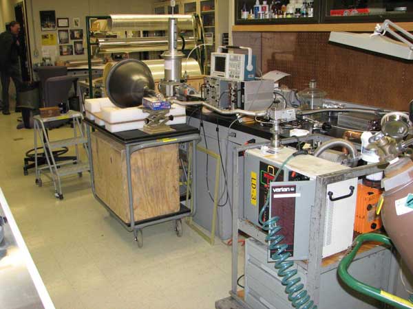
DAY 1: JUNE 10,
2008 HAWKEYE PICTURE TUBE CO. DES MOINES IOWA
The day
begins early at Hawkeye Picture Tube Co. when owner-operator Scott Avitt
arrives for the days work at 3:30 a.m. A somewhat bleary-eyed and sleep
deprived John Folsom, Bob Galanter, and Pete Deksnis arrived at 3:30
a.m. to find Scott already at work.
The plan was to rebuild the two CRTs I
had sent Scott, a 15GP22 and a 19VP22. The previous afternoon Scott had
prepared the CRTs by giving them a thorough cleaning to remove the
external aquadag coating, dirt, and debris, which might tend to foul the
oven.
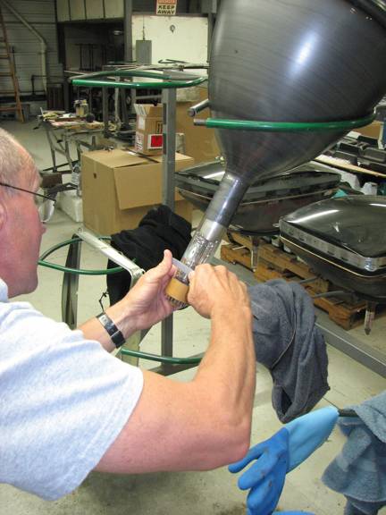
The first task was
to let air into the CRTs, both of which were still under vacuum. Scott
used a compressed air drill with a smooth pointed carbide bit. The bit
is held against the neck of the CRT near the base, and the high-speed
rotation and pressure causes enough friction to melt a very small hole in
the glass. Once the pointed tip of the bit penetrates the glass, it is
withdrawn and air begins to enter the tube. It takes 10 to 15 minutes
for the tubes to equalize with the outside air pressure. Once at ambient
pressure, Scott scores a line on the neck of the tube with a diamond file
and places a nichrome hot wire around the neck of the tube. When the
wire is heated ,it causes the scratch made by the file to propagate
around the neck of the tube, resulting in a clean cleavage of the glass.
Scott extracts the old gun and then washes out the neck of the tube to
remove the old getter material.
SCORE THE NECK
HOT WIRE
THE OLD GUN
NECK WASHING
Next, the CRTs were
placed ina warming oven at approximately 180-degrees F to prevent
condensation while Scott prepares to weld a new length of neck glass onto
each tube. This welding is performed in a vertical lathe, where the CRT
is held stationary and the gas flames rotate around the neck of the tube.
THE VERTICAL LATHE
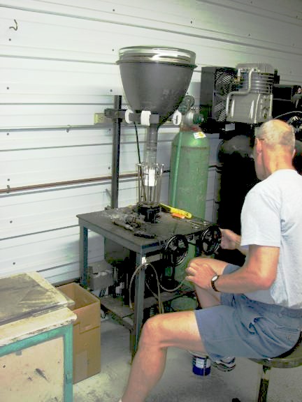
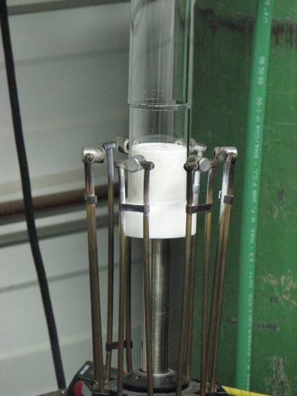
The CRT is
suspended from above, and the new piece of neck glass rests on a Teflon
necking pin, which sits atop a chuck. The steering wheels in front of
Scott allow him to move the chuck or rotating flames up and down.
ALIGNING NECK GLASS IN
LATHE
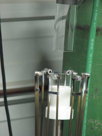
POSITION GLASS FOR
WELDING
FLAME ON!
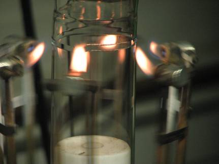
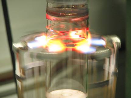
As the flames
rotate, Scott raises and lowers them to slowly heat the glass above and
below the area to be welded in order to prevent thermal shock and
breakage. As the glass warms, Scott slowly raises the temperature of the
flames, and decreases the up/down travel.
GETTING HOT
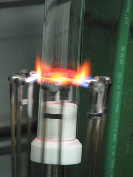
When the edges of
the two glass pieces reach the right temperature, Scott raises the chuck
until the edges touch, and the weld is made.
MAKING THE JOINT
The joint is slowly
cooled under the flames, annealing the glass to relieve stresses built up
by the temperature gradient.
COOLING OFF
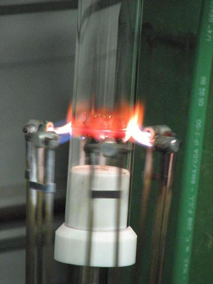
THE WELD IS
COMPLETE
Next, the new gun
is positioned in the neck of the tube. Scott made measurements and marks
on the CRT prior to removing the old gun to let him know where to
position the new gun in the neck. The gun is held rather tightly in
place by little springy fingers mounted around the gun. Scott folds the
wires on the button tight against the stem so they will fit inside the
chuck on the vertical lathe.
NEW GUN
The CRT is placed
atop a hotbox at about 550-degrees F with the neck and gun inside the
box. This thermally prepares the neck and gun assembly for sealing the
button into the neck. The button is the round piece of glass through
which the wires extend. The stem is the hollow piece of glass at the
center of the button through which the CRT is evacuated.
THE HOT BOX
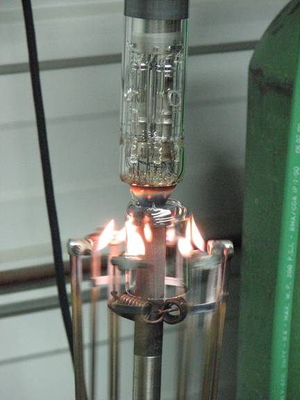
Now back into the
vertical lathe to weld the new gun in place. The end of the chuck is a
hollow conical shaped metal piece, which Scott raises to be flush with
the bottom of the button. The evacuation stem with the wires pressed
against it fits down inside the center of the chuck. The cone supports
the button and shields the wires and evacuation stem from the heat of the
flames. In a manner similar to the procedure for the neck extension
weld, the glass is slowly heated until it reaches the proper temperature.
READY TO SEAL
HEATING
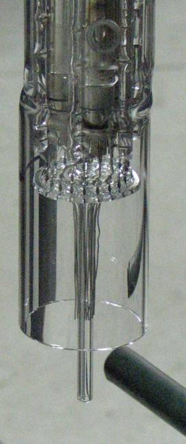
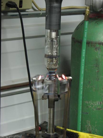
As the neck glass
continues to heat, it eventually reaches a temperature where it softens
to the point that it begins to stretch out under the influence of
gravity. The glass below the heated area falls until it is stopped by the
spring wrapped around the chuck. As it falls, the neck glass
stretches out, thins, and pulls inward until it makes contact with the
edge of the button. The amount of "fall" is critical and is controlled by
the placement of the spring on the chuck. Scott continues to pour on the
heat, and the neck glass fuses to the rim of the button. The thin curtain
of glass below the button is broken as Scott blows puffs of air
up through holes in the chuck. This, along with the action of the flames,
cuts off the curtain of glass.
THE FALL
Once again, the
glass is cooled slowly under the flames.
COOLING
THE BUTTON IS
SEALED INTO THE NECK
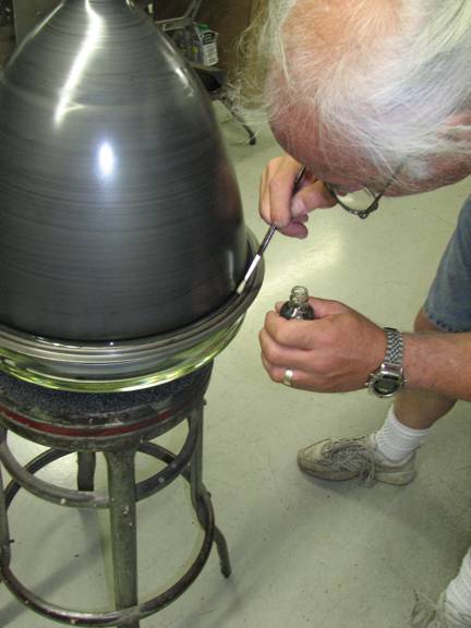
Next, Bob Galanter
applies a bead of VACSEAL to the glass-to-metal seals on both sides of
the metal flange at the face of the CRT.
VACSEALING
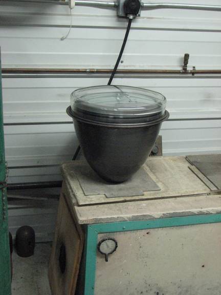
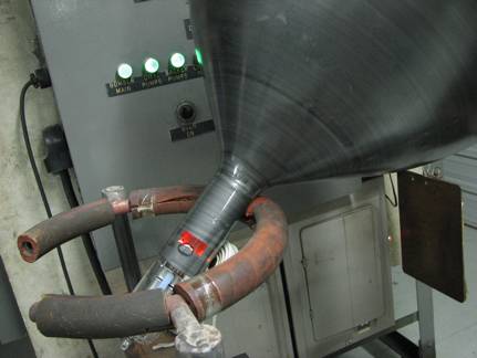
The CRT is placed
on a rack in the exhaust cycle oven.
THE OVEN SETUP
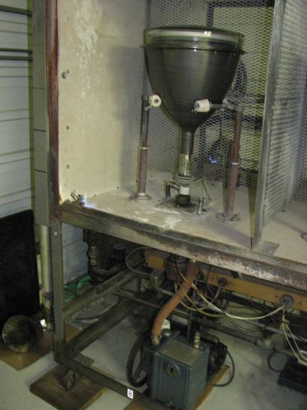
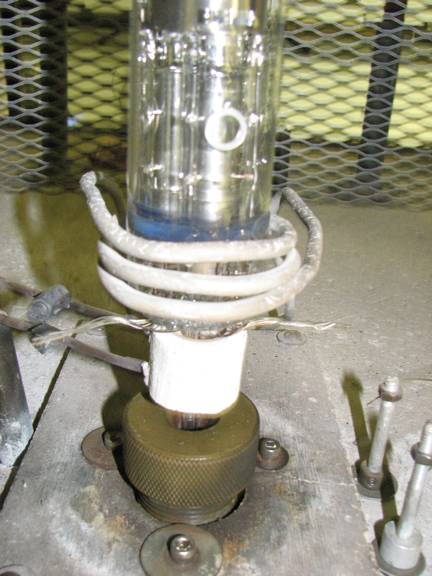
The CRT is
suspended in a holder in the oven above the exhaust port. The port is
connected to the vacuum pumps below the floor of the oven. A mechanical
pump draws outmost of the air from the CRT, while a diffusion pump
achieves the very high vacuum required for CRTs to operate. The stem of
the CRT fits down into the open hole of the exhaust port. A rubber
bushing slides tightly onto the stem, with a knurled threaded cap above
it. When screwed down onto the port, the cap compresses the rubber
bushing makes a vacuum-tight seal with the glass stem. The whole port
assembly is cooled by a water jacket. Above the port on the stem is a
pinch-off coil. This is an electric heating element that is energized at
the end of the exhaust cycle. Heat from the element softens the glass
stem until air pressure causes the stem to collapse, pinching off the
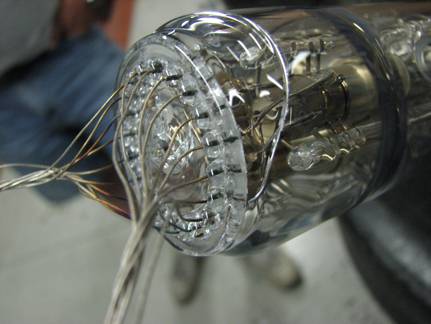
vacuum in the CRT. Note that the button wires are now flared out to allow
the pinch-off action to be close to the button. Around the neck of he
CRT is the so-called bomber, a RF induction coil used to heat the
elements of the gun during the evacuation cycle to drive out more of the
stray gas molecules.
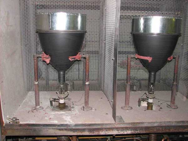
OVEN SETUP
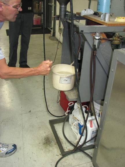
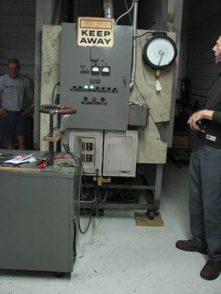
The gas-fired oven
is controlled by a simple cam and leaver system driving a sequence of
relays to activate the various steps in the exhaust cycle.
THE CAM
OVEN CONTROL AND
STATUS INDICATORS
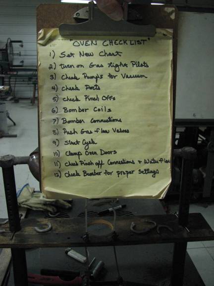
Scott has a
checklist he follows religiously for each position in the oven prior to
initiating the exhaust cycle. One the cycle starts it must run to the
end. Scott can override some actions in the cycle for each station in
the oven, such as the vacuum pumps, bomber coil, or pinch-off coil
operation, should there be a problem with a particular CRT while in the
oven.
THE CHECKLIST
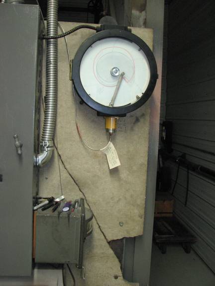
The arm rides along
the spiral edge of the cam and controls the oven temperature. The cam
rotates once in about three hours and slowly increases the oven
temperature to approximately 650-degrees F. Scott then flips the cam
over, and the oven begins to cool during the following three-hour period.
The exhaust cycle
starts with activating the vacuum pumps and bringing the oven up to
temperature. Then the bomber coil is activated, further heating the gun
elements and improving the quality of the vacuum. As the oven cools,
the pinch-off coil is activated, sealing off the vacuum in the CRT. The
oven is left to cool completely overnight.
DAY 2: June 11, 2008
Scott
took pity on us and told us we could sleep in until 4:00 a.m. the morning
of the second day. We arrived full of anticipation. "Bad news" announced
Scott as we entered the door. About an hour into the oven cycle,
when the temperature had reached about 600 degrees F, Scott heard a
whistle from the15GP22 station in the oven. He turned off the vacuum
pumps, bomber coil, and pinch-off coil for that oven station and allowed
the oven to complete the exhaust cycle. The 19VP22 and 12UP4 CRTs ,
which occupied two other stations in the oven, completed the exhaust
cycle nominally.
We opened the now
cool oven and examined the 15GP22. The failure occurred right where the
stem joined the button. This was possibly caused by a shift inthe CRT
position on its holder in the oven, or from a build up of lateral forces
on the stem during the heating.
THE DAMAGE
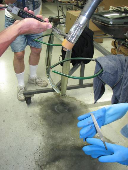
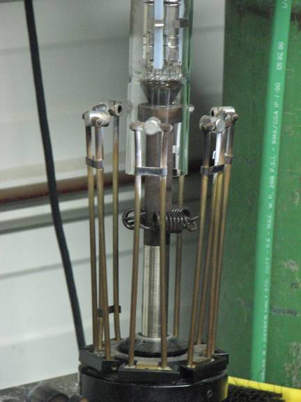
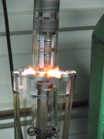
For the 19VP22 CRT,
the next step was to flash the getters. The horseshoe shaped ring is an
RF induction coil used to heat the getters, causing the oxygen scavenging
material in the getter to boil off and deposit on the inside surface of
the neck of the CRT. This helps to further improve the quality of the
vacuum in the CRT.
FLASHING THE
GETTERS
Next, high-voltage,
pulsed-AC is applied to all the pins of the CRT while the anode is tied
to the AC return. This is done to burn out any residual debris within the
gun structure. Then the cathodes are activated by heating them using
elevated voltage applied to the filaments. Last, a new base is soldered
to the wires of the button and affixed with silicone RTV.
THE WAY FORWARD
The failure of the
15GP22 is both good and bad news. It is, of course, bad news that it did
not make it through on the first attempt. But the stem failure is
mostly good news, as this type of failure is uncorrelated to the fact
that it is a 15GP22. This failure can likely be corrected by ordering
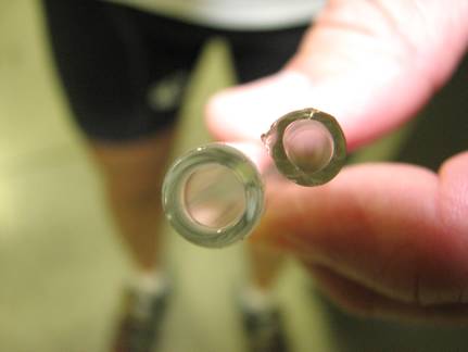
stems with a stouter tubulation. Back in 2003 when Bruce Buchanan and I
were first discussing this with Scott, he indicated to Bruce that a 0.25"
O.D. tubulation was what he wanted on the stems. But this now seems to
have been a miscommunication of some sort between Scott and Bruce. So
new stems will have to be ordered. The good news, they are still
available.
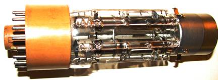
This photo
illustrated the differences in the tubulation on our stem (right)
compared to the now preferred tubulation (left).
TUBULATION
The VACSEAL cured
very nicely, and though this tube did not have a leak, this seems to
offer some hope that VACSEAL may be useful in stopping leaks. But this
will have to be proven when the day comes to attempt a rebuild of a
leaker CRT.
In order to rebuild
a 15GP22,you need a replacement gun. However, no new or new-old-stock
guns for the 15GP22 are available. South West Vacuum rebuilt two 15GP22
guns for me by replacing the heaters and cathodes and attaching the
rebuilt gun to the new button. But this service is not longer available
from South West Vacuum. While attempting to seal in the first of these
guns into the15GP22, Scott failed to achieve a proper seal between the
button and the neck, so he cut the first gun out and used the second
gun. This leaves us with no rebuilt guns.
After removing the
failed CRT from the oven, the gun was removed and the CRT sealed with a
resin tape to prevent moisture from getting in. It now awaits the next
rebuilding attempt.
The two 15GP22 guns
removed are undamaged, and the cathodes are still good. However, they
are both now attached to damaged buttons which cannot be reused. In
order to put a new button on, it is necessary to remove the heaters and
cathodes and replace them with new ones, because the structure of the
heater and cathode attachments to the button wires are too frail to
survive any attempt at a button transplant.
Bob Galanter has
taken on the task of attempting to rebuild guns for the 15GP22. Our
research so far leads us to believe it is doable. In parallel, we are
pursuing a solution from the French CRT company RACS.
But the clock is
running….Scott will retire in about two years, so we would like to
squeeze in as many rebuilds as possible.
Stay tuned for
future developments!
Rebuilding the 15GP22: A Final Report
Late in February 2010, Bob Galanter and I traveled to Hawkeye Picture Tube Co. in Des Moines, IA to have another go at rebuilding 15GP22s. Bob and I each brought an under vacuum dud tube, and a known leaker tube. The plan was to rebuild the two tubes that were under vacuum, and have Scotty install dummy guns and stems on the two leakers, so we could take them to a Michigan University lab for leak testing.
We had with us some of the redesigned Richland stems used successfully to rebuild the first 15GP22, and several rebuilt 15GP22 gun assemblies mounted on the new style Richland stems.
Scotty first installed the dummy guns and stems onto the two
leaker tubes without incident. Next he installed rebuilt 15GP22 guns onto the two under vacuum 15GP22s. One of the two stems that were mounted to the
under vacuum tubes, cracked while the tube was cooling down. We had extra guns, and the second attempt was successful.
The two "non-leaker" tubes went into the oven and began the baking and evacuation cycle. Bob's tube had aluminum filled high temperature epoxy applied to the glass to metal joints around the flange of the tube. My tube had vacseal applied to the same areas.
Within a couple of hours, the mechanical backer vacuum pump was making gurgling noises. (this sound from the pump is a sign that a tube is leaking) The pump for Bob's tube was turned off. Bob and I went to the motel room for the evening.
In the morning, Scotty informed us that my tube had also failed in
the oven, during the tip-off cycle. Tip off is is where a electric heating element heats the glass exhaust stem and causes it to melt and collapse, sealing the tube shut. Opening the now cool oven door revealed the following damages.
Bob's tube had failed because the epoxy material's difference in temperature coefficient of expansion, had pulled up flakes of glass from the surface, which propogated a crack around the face of the CRT, at the glass to metal joint. A whack with a rubber mallet separated the faceplate from the front of the CRT.
My CRT had failed due to a crack in the stem. And in addition, there was a crack in the phosphor dot plate. So this leaves both of these tubes destroyed.
Later that week Bob and I took the 2 leaker CRTs and a curing oven to a Michigan University lab where leak testing was performed using a helium leak detector. This equipment consists of a mechanical vacuum pump and a turbo-vacuum pump, which can evacuate the CRT rapidly, and a mass spectrometer that looks for the presence of helium in the exhaust from the CRT.
Leak checks on Bob's tube revealed two closely spaced leaks at the edge weld where the 2 metal flange pieces were heli-arc welded together. Leak checks on my tube revealed leaks at the glass to metal seams.
Bob attempted to seal the leak in his tube by apply a non-filled version of the high temperature epoxy, but it was not
possible to keep the epoxy in place on the leaks where we wanted it, and so the attempt to seal these weld leaks failed.
We put vacseal on the glass to metal joints on my tube, and within the limits of the equipment, it appeares that the leaks have been sealed.
We had also brought with us, a 21AXP22 CRT which Scotty had previously rebuilt for me, which had leaked after removal from Scotty's oven. Leak checks on this tube revealed a leak at the flange weld line on this tube. These leaks in the welds on the CRTs was unexpected, and adds a new level of complexity to our problems.
Bob and I returned to our respective homes, and the three leaker CRTs stayed with Bob. He began some experiments on a flange from a broken 15GP22 to see if he could braze the flange weld. Preliminary results are encouraging.
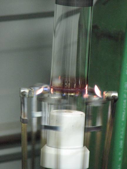
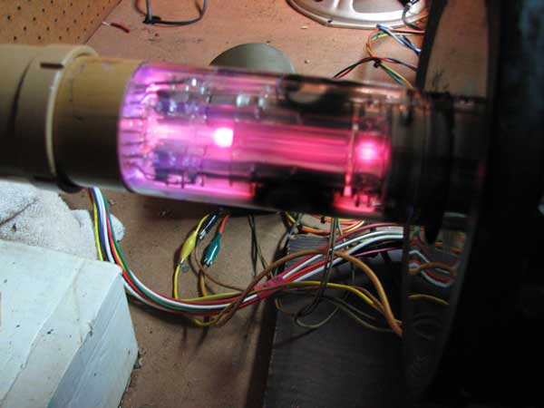
Today I was troubleshooting a strange and difficult to isolate high voltage arcing problem with my Motorola 15" color set. I decided to use the only successfully rebuilt 15GP22 from our attempt back in November of 2009, to determine if the problem was with the Motorola CRT or mounting fixture. Both the Motorola CRT and the rebuilt 15GP22, are mounted on slide-in wooden CRT holders, so it was easy to simply swap CRTs on their holders, and put the Motorola yoke on the rebuilt CRT.
Upon power up, there was no raster. A few quick checks revealed a dreadful purple glow in the neck of the rebuilt 15GP22! Argggggh! The tube has sprung a leak.
Discussing this with Bob, and considering everything we have done to date, and the fact that we still have unresolved stem cracking issues, we agree that we can no longer justify the expense of additional attempts to rebuild tubes. Maybe in the future, if CRT rebuilding can be set up at the ETF museum, and the overhead cost of rebuild attempts becomes much lower, we may consider continuing the effort. But for now at least, I think we have done all that we can justify doing.
