
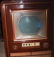
| The Set: Pete Deksnis's Site about the CT-100 Restoring a Vintage Color Television Set |
This page describes CTC-2 production changes to boost B+
[The
exact serial-number range of this production change is as yet unknown.
But, the modification appears fairly early in the production run.]
-----
To determine if a CTC-2 chassis has the original or revised boost B+ circuit, remove the high-voltage cage cover. In the high-voltage cage, check Terminal 1 on the flyback transformer.
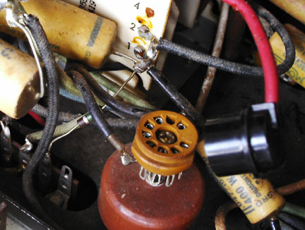
If there is more than one connection on flyback terminal 1 as shown above, the chassis has the revised boost B+ circuitry. If the set has only a 0.047-uF paper capacitor connected to terminal 1, the set has the original boost and vertical oscillator circuit. This 'boost B+' capacitor, which is used in both the original and revised circuit, is shown partially hidden by the focus rectifier plate cap in the lower right-hand corner of the above graphic.
-----
Documentation for the CT-100 – such as Sams Photofact 252 and Telaide RCA Volume Two – describes only early-production boost B+ and vertical oscillator circuitry.
Production modifications to these original circuits are described in four steps below the next graphic. There are six components involved in these flyback circuit modifications. Four of the six components are new, one changes value, and one changes its connection. The other two boost components remain unchanged.
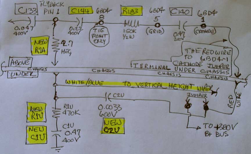
Four new components, one value change, and one circuit change in a revised CTC-2 chassis.
Note that locations of these components, their connection points, and the photos are from the perspective of a CTC-2 chassis that came off the production line with these modifications in place.
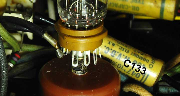
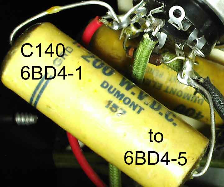
1. The following components do not change from those values and connections that appear in traditional early-production CTC-2 documentation. Sams reference designations: C133, C140.
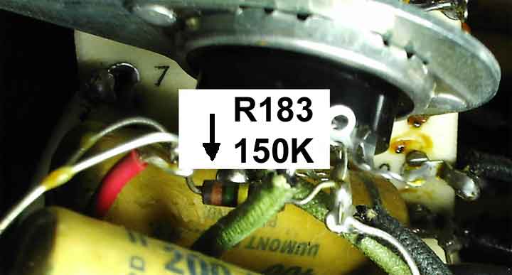
2. The following component does change from the value that appears in traditional early-production CTC-2 documentation. Sams reference designation R183 changes value from 1 megohm to 150K (remains ½-watt carbon).
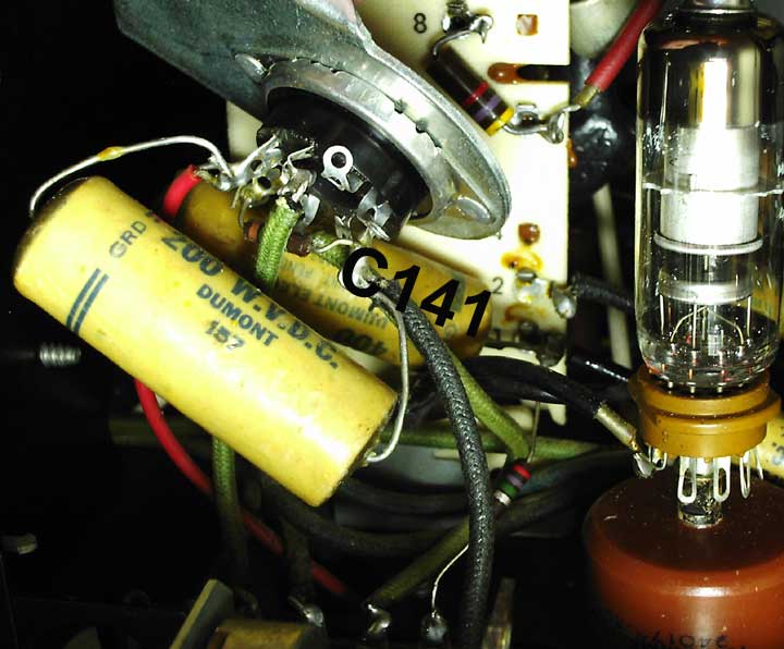
3. The following component does change from its connection in the circuit that appears in traditional early-production CTC-2 documentation. Sams reference designation C141 no longer goes from 6BD4 pin 8 to ground. C141 now goes from 6BD4 pin 8 to flyback terminal 1. Note: C141 is mislabeled in the above diagram as C144; the Times regrets the error.
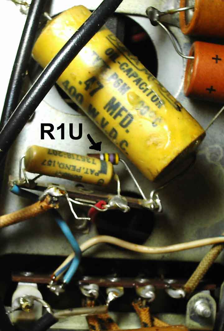
4. The
following four components are added
to those values and connections that appear in traditional early-production
CTC-2 documentation. Using newly assigned reference designations, each contains
a suffix that specifies an above-chassis component or underneath-chassis
component.
R1U:
470K ½-watt carbon. This component is electrically connected between the
R1A/C2U/R3 junction and C1U.
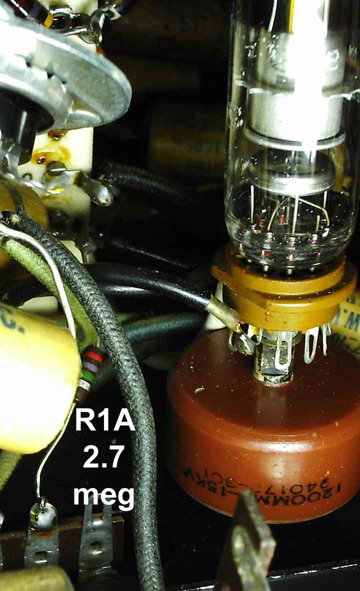
R1A:
2.7 megohm ½-watt carbon. This component is electrically connected between
flyback pin 1 and underchassis R1U/C2U/R3 junction.
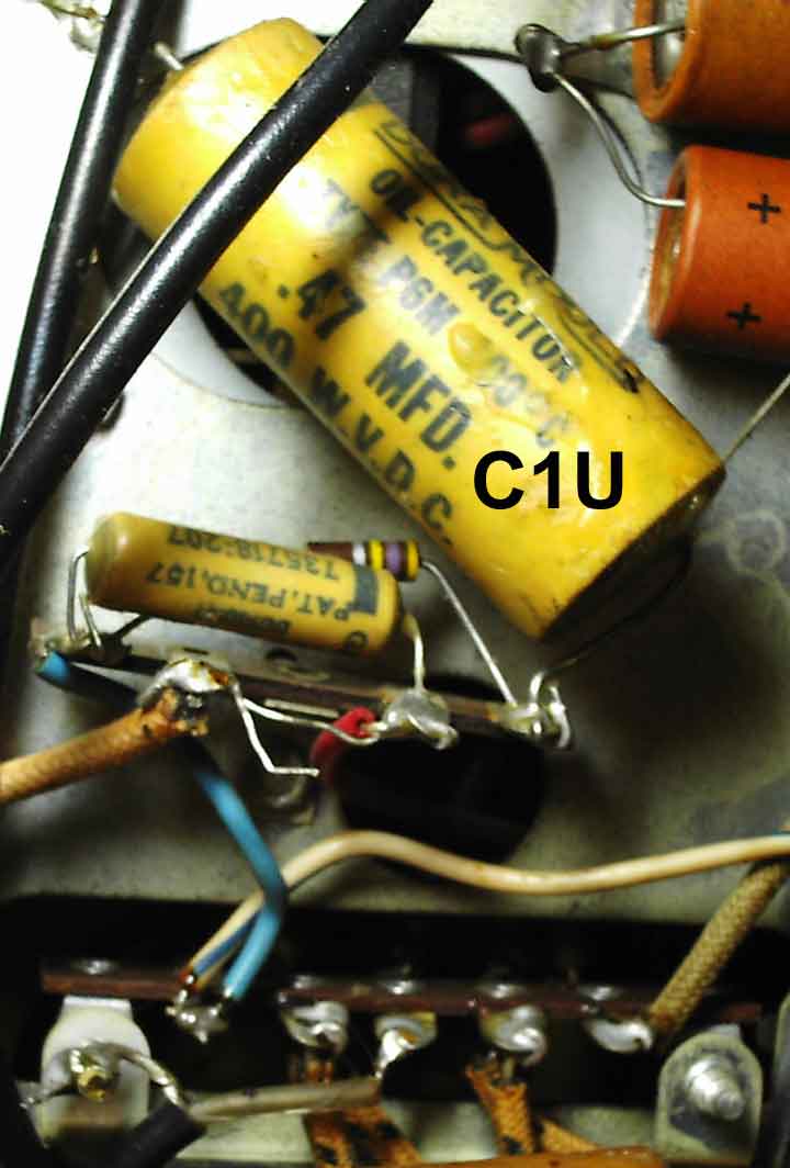
C1U:
0.047 uF 400V. This component is
connected between R1U and ground.
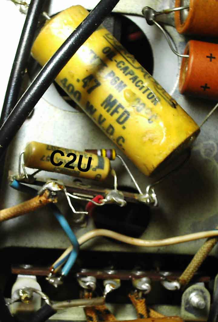
C2U:
0.0033 uF 600V. This component is electrically
connected between the underchassis R1A/R1U/R3 junction and an underchassis tie
point from 6BD4 pin 1.
In addition to this revised boost circuit, boost B+ is now connect directly to the wiper of the height control. Accordingly, R144 (Sams) was eliminated. A second vertical oscillator circuit resistor, R143, changes value from 1.5 to 1.2 megohm.