Early Television  
Mechanical TV History How it Works Mechanical Sets at the Museum Gallery Database Summary Broadcasting Technical Inforation Restoration Advertising Articles Roger DuPouy's Site Peter Yanczer's Site Gerolf Poetschke's Site Eckhard Etzold's Site
Early Electronic Television History American Sets at the Museum British Sets at the Museum Gallery Database Summary Broadcasting CRTs Accessories Technical Information Restoration Advertising Articles Gerolf Poetschke's Site Eckhard Etzold's Site
Postwar American TV History American Sets at the Museum British/Europen TV History British/Europen Sets at the Museum TV in the Rest of the World Gallery of Unusual Sets Broadcasting CRTs Accessories Technical Information Restoration Advertising Articles Eckhard Etzold's Site
Early Color TV History Sets at the Museum Gallery Database Summary Broadcasting CRTs Accessories Technical InformationRestoration Advertising Articles Pete Deksnis's Site Ed Reitan's Color Television History Eckhard Etzold's Site
The Early Television Foundation About the Museum Directions to the Museum Articles about the Museum Support the Museum Join our Email List Our Newsletter - "What's New in Old TVs" Equipment Donations Museum Members and Supporters Members Only Monthly Online Meetings Annual Convention Swapmeets
What's New on the Site Classifieds Parts for Sale Resources North American Radio and TV Museums Search the Site
Contact Us FacebookYouTube Channel
 

Early Television

Home Page

The Set: Pete Deksnis's Site about the CT-100

Restoring a Vintage Color Television Set

THE SET 6SN7 Horiz. Osc. Restoration

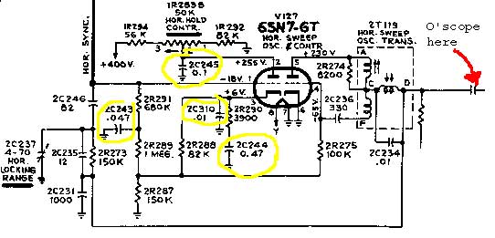
Replace four paper capacitors with modern equivalents

Early Television 
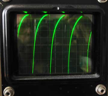
With an external power supply connected to the "+400V" point on this schematic AND to the 68K 1/2-watt resistor [2R267 RCA; R174 Sams] on terminal "D" of the horizontal sweep oscillator transformer (that 'floating' resistor shown on the schematic), you can check for the waveform below [Sams W16]. You may be able to vary the period -- use the horizontal hold control -- around the 63-microsecond horizontal line period. If not, the slug on top of the horizontal sweep oscillator transformer may require adjustment.


Early Television

NOTE: Isolate the 6SN7 circuit from the rest of the CTC-2 chassis for the above test as follows: Disconnect both resistors from the B+ bus before applying power to this circuit.
(a.) 56K 1R294 is located above the chassis behind the horizontal hold pot.
(b.) The hot end of 2R267 is easily lifted from its tie point underneath the chassis.

The ballast assembly that plugs into a socket on the back of the rectifier cage should NOT be installed.

------------------
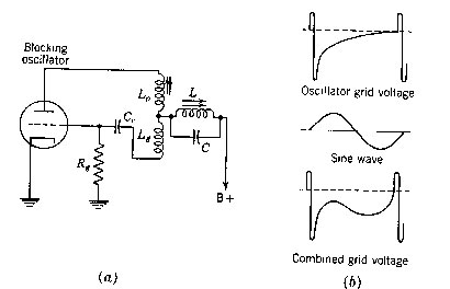
At terminal "C" of 2T119, the horizontal sweep oscillator transformer, you will see [Sams W15] a characteristic SynchroLock waveform "Combined grid voltage" as illustrated in this 1954 graphic from a Grob color TV textbook.
------------------

Early Television

[Return]


Early Television Museum
5396 Franklin St., Hilliard, OH 43026
(614) 771-0510
info@earlytelevision.org