Early Television  
Mechanical TV History How it Works Mechanical Sets at the Museum Gallery Database Summary Broadcasting Technical Inforation Restoration Advertising Articles Roger DuPouy's Site Peter Yanczer's Site Gerolf Poetschke's Site Eckhard Etzold's Site
Early Electronic Television History American Sets at the Museum British Sets at the Museum Gallery Database Summary Broadcasting CRTs Accessories Technical Information Restoration Advertising Articles Gerolf Poetschke's Site Eckhard Etzold's Site
Postwar American TV History American Sets at the Museum British/Europen TV History British/Europen Sets at the Museum TV in the Rest of the World Gallery of Unusual Sets Broadcasting CRTs Accessories Technical Information Restoration Advertising Articles Eckhard Etzold's Site
Early Color TV History Sets at the Museum Gallery Database Summary Broadcasting CRTs Accessories Technical InformationRestoration Advertising Articles Pete Deksnis's Site Ed Reitan's Color Television History Eckhard Etzold's Site
The Early Television Foundation About the Museum Directions to the Museum Articles about the Museum Support the Museum Join our Email List Our Newsletter - "What's New in Old TVs" Equipment Donations Museum Members and Supporters Members Only Monthly Online Meetings Annual Convention Swapmeets
What's New on the Site Classifieds Parts for Sale Resources North American Radio and TV Museums Search the Site
Contact Us FacebookYouTube Channel
 

Early Television

Home Page

The Set: Pete Deksnis's Site about the CT-100

Restoring a Vintage Color Television Set

THE SET

12BH7 Vert. Osc.-Amp. Restoration

Replace seven paper capacitors with modern equivalents


C104(Sams) / 1C242(RCA) = 0.1 uF
C105(Sams) / 1C241(RCA) = 0.22 uF
C106(Sams) / 1C238(RCA) = 0.15 uF
C107(Sams) / 1C240(RCA) = 0.001 uF (1600v)
C108(Sams) / 1C212(RCA) = 0.47 uF
C109(Sams) / 1C211(RCA) = 0.22 uF
C110(Sams) / 1C210(RCA) = 0.1 uF

Four of the seven capacitors appear in the photo.

Early Television

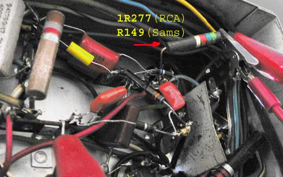
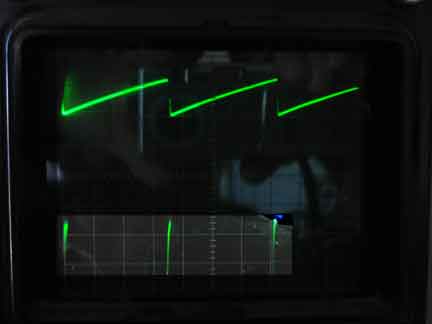
With an external power supply connected to the 5.6K 2-watt power resistor [1R277(RCA); R149(Sams)] shown in the photo above AND to the 4.7K 1/2-watt resistor [1R301(RCA); R144(Sams)] on the wiper of the Height control AND with the yoke assembly plugged into the octal socket on the back of the high-voltage cage, you can check for the waveform below [Sams W10].

Early Television

NOTES: Isolate the 12BH7 circuit from the rest of the CTC-2 chassis for the above test as follows: Disconnect both resistors from the B+ bus before applying power to this circuit.

(a.) 5.6K 1R277 is located below the chassis as shown in the photo above.
(b.) The hot end of 1R301 is easily lifted from its tie point underneath the chassis; that resistor is found a few inches to the left and below the first resistor.

The ballast assembly that plugs into a socket on the back of the rectifier cage should NOT be installed.

[Return]


Early Television Museum
5396 Franklin St., Hilliard, OH 43026
(614) 771-0510
info@earlytelevision.org