
|
Vintage Television Sets and Colour Television Sets from the Dawn of Television until Now
Echard Etzold's Site |
|
Color TV:
Documentation: Color image control receiver of the "Operational Laboratory for Radio and Television" of the Central Radio and Television Office of the Deutsche Post (RFZ)
Construction year: ca. 1963
Click on the photo to enlarge it!
|

|
As color television slowly established itself in the United States, technicians in Europe began testing color television. To this end, they designed and built their own color monitors, some of which were based on American technology, but which met the new requirements in Europe. One such example is the color image control receiver of the "Works Laboratory for Radio and Television" from the GDR, probably developed around 1963. (This date is noted on the electrolytic capacitors - however, the circuit diagram already has a printing permit number from 1960). This color picture control receiver is probably the only remaining device from the early days of color television development. There are even reports of these attempts from that time. |
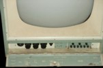
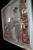
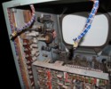
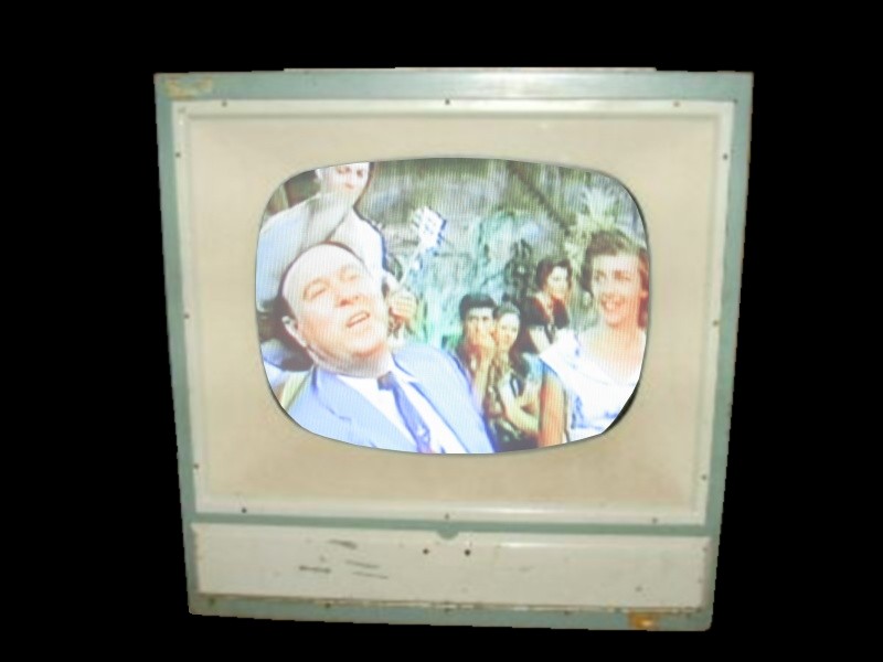
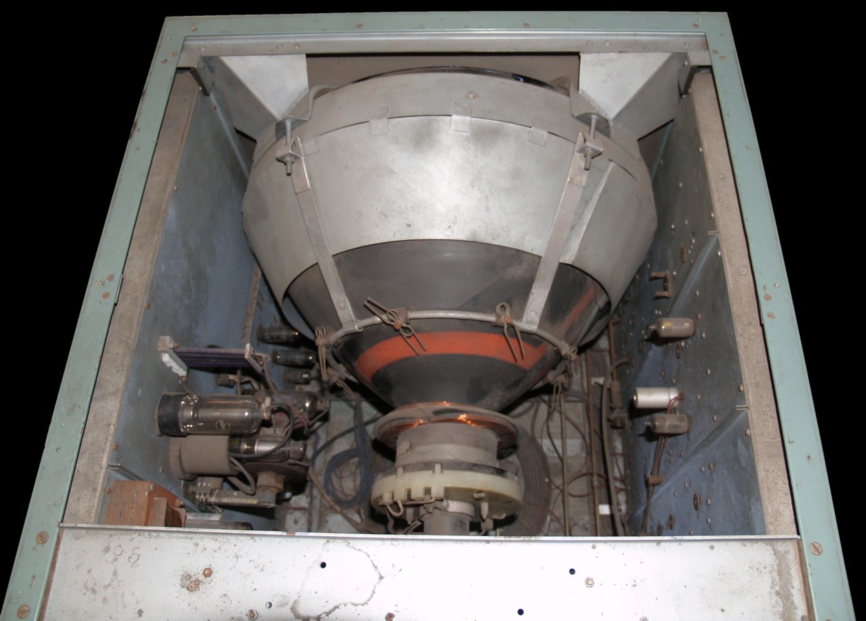
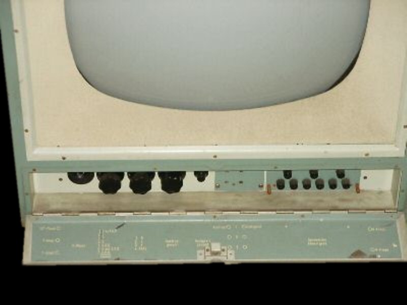
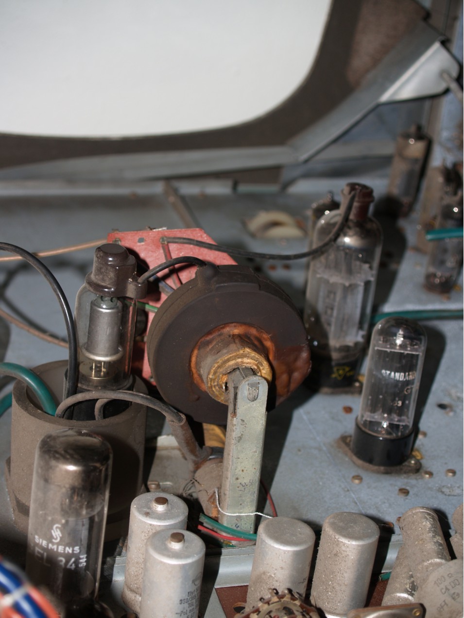
Although the color image control receiver has an American round picture tube (21CYP22), the image section is selected to be rectangular, in accordance with German viewing habits. The controls for operation are hidden behind a hinged flap on the front. A look from above into the color image control receiver shows the massive picture tube, which is held in place by sheet metal frames and braces.
|
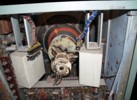
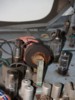
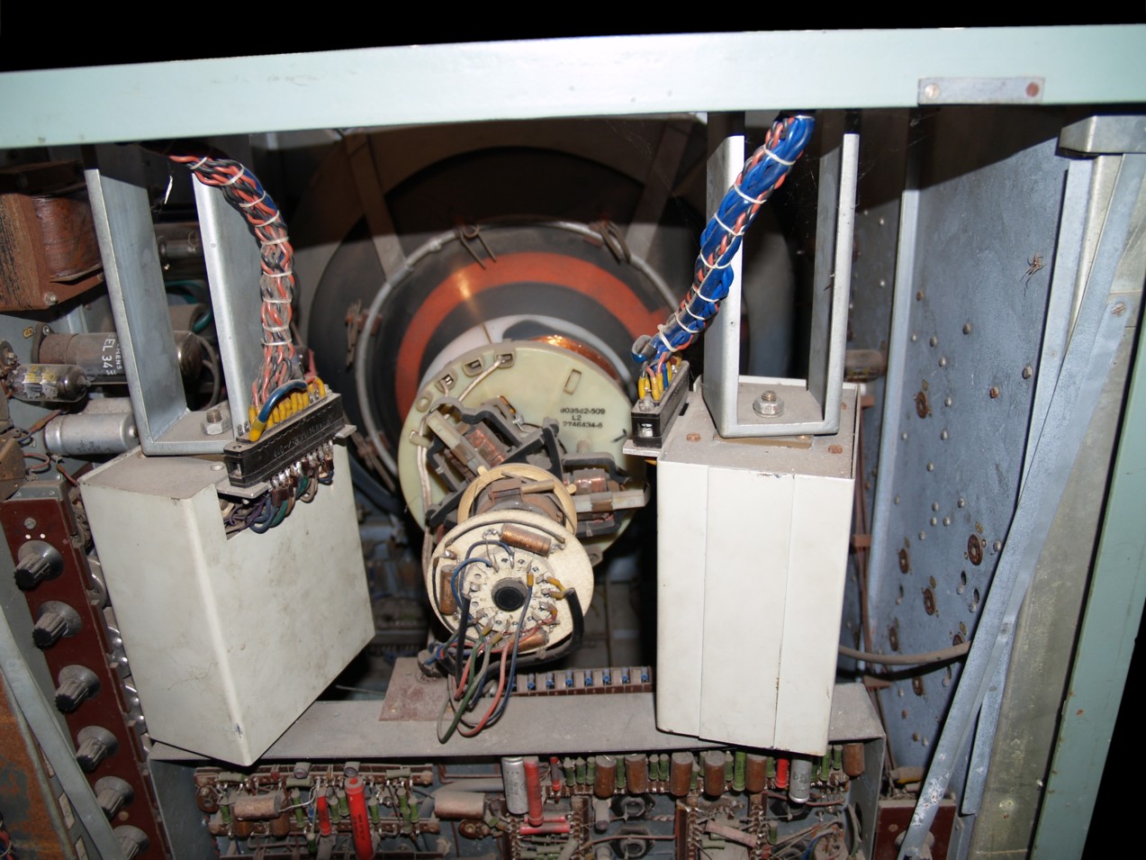
The view from behind shows the deflection yoke with the high voltage supply on the left. The color output stages can be seen in the lower area. The tubes are missing in the right part. An NTSC signal (or an NTSC modification) is implemented here, which was probably no longer in use later. The missing tubes suggest this. It is possible that the color image control receiver was only operated with composite video signals when the GDR decided in favor of the SECAM process.
|
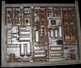
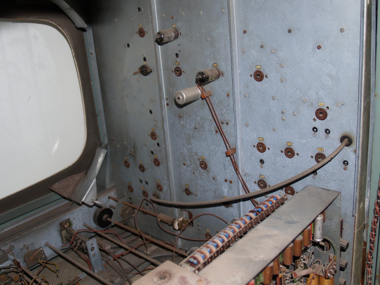
The exact number of tubes has not yet been determined, but it exceeds the number one would normally expect to find in a color television monitor. The power supply is very generously designed and ensures a clean DC voltage with extensive capacitor banks. Eight EC360 series regulators stable voltages. The tube filaments operate on 6.3 volts, based on the American model.
|
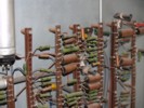
The horizontal output stage corresponds completely to the American technology of the late 1950s, with a rectifier tube for the high voltage and a HV regulator. 6DQ5 and 6AU4GTA are the output stage tube and the damper, EY51 is the focus rectifier, 3A3 is the high-voltage rectifier tube and 6BK4 is the HV regulator. These tubes (as well as the picture tube) were imported directly from the USA. Components and circuit technology suggest that the RCA chassis CTC-9 served as a model.
|
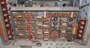
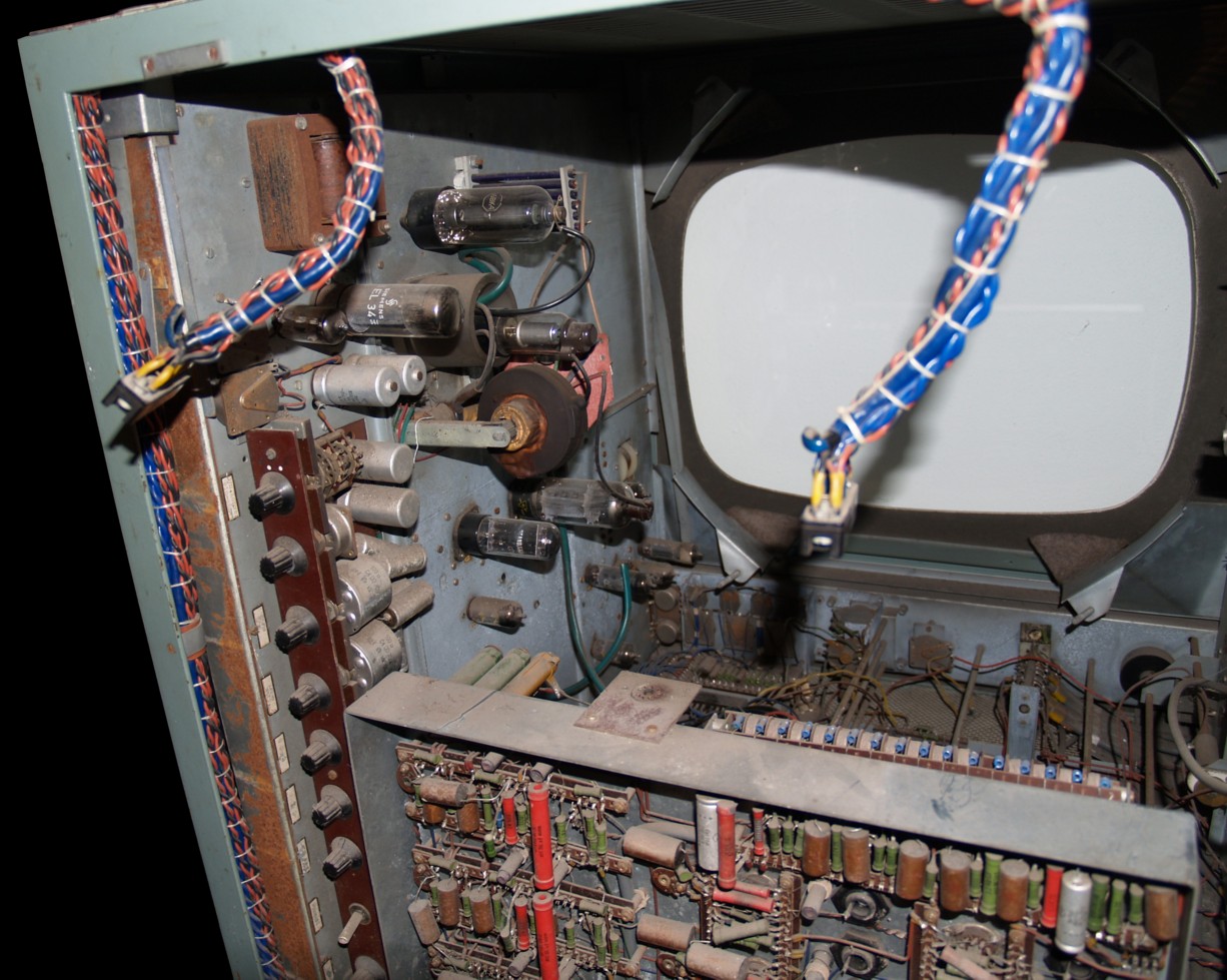
Circuit boards were not used. The circuits have been neatly done by hand with soldering strips. In the lower part of the left photo, the RGB signal inputs can still be seen clearly with their labeling. The following note is informative about the history of color television development in the GDR:
"As early as the end of 1960, Deutsche Post had experimented with color television - at that time still on the basis of the American NTSC system: 'In collegial cooperation, especially with the scientists and engineers of the USSR, (...) Color television will also be introduced in the GDR. (...) In doing so, we will avoid mistakes or, better still, capitalist customs such as can be found in the USA. ' - claimed Kurt Hein: The color picture will come. In: Neues Deutschland from June 13th, 1960. As early as 1963 a 'color television test studio' was set up and technology was developed for the technical test broadcasts: 'RGB mixing amplifier QV 603', 'video distribution amplifier QV 604 ',' Color Correction Amplifier QV 605 'and a' RFZ-Farbfernseh-Epiabtaster '. About these first experiments and investigations in more detail in word and picture Wobst, J .: Das Farbfernsehversuchsstudio des RFZ. In: Technische Mitteilungen des RFZ 3/1964, Pp. 122-124. "
|
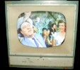
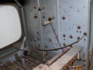
The cabinet and contacts are already showing severe corrosion damage. There is still a lot of work to be done before the color image control receiver is functional again. The picture shown at the left is not an actual image on the monitor.. But the chances that this color image control receiver will deliver a clean picture again are not so bad, because the picture tube still has excellent beam current properties - an indication that this color image control receiver has not been used often.
|
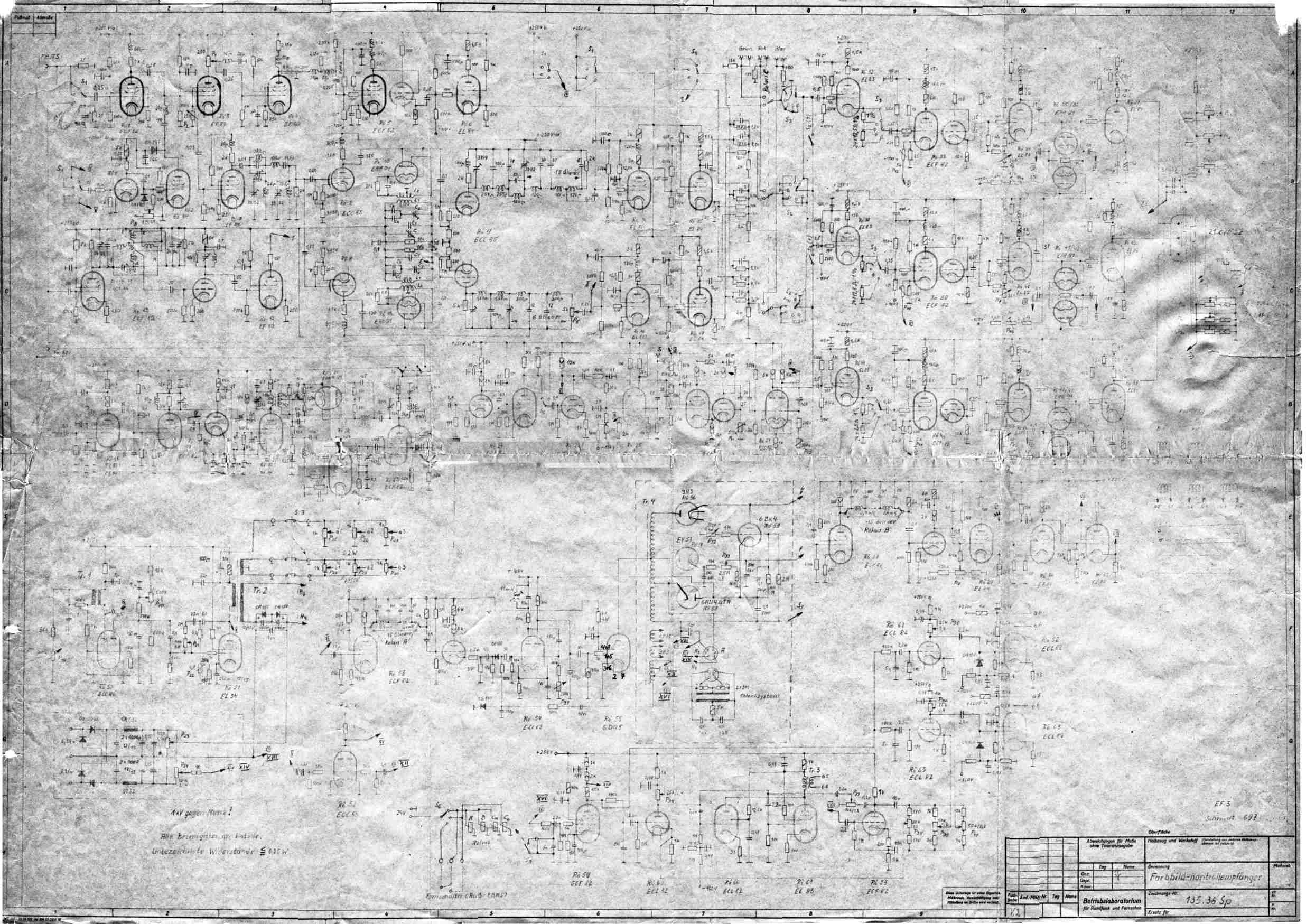
Circuit Diagram
Click here, 320 KByte. The circuit diagram is available in a better resolution and quality via email request.
Tubes
21CYP22,
5 - EC85, ECC82, 6DQ5, EY51, 6BK4, 6AU4GTA, 3A3, 11 - EL84, 3 - EAA91,
3 - ECL82, 6 - ECC85, 4 - EL83, 7 - ECF83, 13 - ECF82, 11 - EF80, 2 - EAA91, 2 -EL34.
Warning: This website offers you an insight into the interior of the device. Please note that the removal of rear walls and covers is reserved for a specialist only. This is especially true when the device is plugged in, in operation or under voltage. Burns or even fatal electric shocks can result! But even if the power supply is disconnected, there is a risk that malicious electric shocks can occur if the procedure is improperly followed. In particular, the picture tube and the assemblies connected to it can still carry a high voltage of well over 10,000 volts hours or days after the last start-up. The author rejects any liability for injuries and damage resulting from the information given here and expressly points out that, for the inexperienced, experts such as electricians or electrical engineers must be consulted before opening devices.
Links:
 Zur Zur
![[Zurück]](Images/arr-supr.jpg)
Stand: 27. Dezember 2006,
|


