|
Television Experimenters.com
Mirror Screw Technology - Page 1
|
Mirror Screw Technology
Following the Nipkow disk patent, many attempts were made to improve on the efficiency of mechanical disk scanners. Lens disks provided larger brighter images, as did mirror drums even more so. However, these methods added greatly to the cost. It was not until 1928, with the
patent by Gardner of the mirror screw, that it appeared that a better solution had been found. The mirror screw was the first to provide images without the scanning line structure plainly visible. Compared to any of the other scanners, it would provide brighter than expected images and produce them as large as itself without any secondary magnification.
Cost-wise, if mass-produced, the cost of a mirror screw scanner would be amongst the lowest. The mirror screw consists basically of an assembly of an axle and a set of permanently adjusted mirrors. This assembly is then
mounted on a motor shaft and that completes the scanner. By far, this is the most simple of all mechanical scanners. However, the mirror screws must be very precise in their construction. The mirrors themselves are all part of a matched set. More like lenses than say a shaving mirror. Made from stainless steel, there is nothing to wear out and it will last indefinitely.
Getting involved in mirror screw technology has been somewhat difficult in past years, partly because of the lack of good historic information but mostly because of the total lack of hardware. If there were more hardware around, most people upon seeing it, would be inclined to find out more about these mirror screws. The site you are looking at right now is as good a source for this information as is available anywhere.
|
Any reluctance might be partly due to the thought that it appears it will cost a lot because of the need to obtain a mirror screw, which because of its rarity, might likely cost as much as a few thousands of dollars. Wow! And that is a lot of money! It's not likely that someone slightly interested could or would justify that sort of expense, without thinking of it for a time.
Let's look at some facts about mirror screws and the cost factors. 1st: Mirror screws are very rare! It is likely that at most, fewer than a dozen original mirror screws exist. 2nd: As for complete original mirror screw receivers, the number must be very low and is likely to be zero. As yet, not even one has been found to exist. In fact, there is no known detailed information available that tells one how to actually build one.
Somewhere along the way, years ago I managed to locate two original mirror screws. One was made of stainless steel and in perfect shape. It weighed 15 pounds and was just under 7 inches on diameter. The other was made of aluminum, about the same size and half the weight. I built two similar receivers, based on a photo of an original German set. The stainless steel screw produced an excellent 120-line picture. The aluminum screw had some corrosion that degraded the picture quality. I later replaced that screw with a
60-line stainless one that I built and it too produced a good picture.
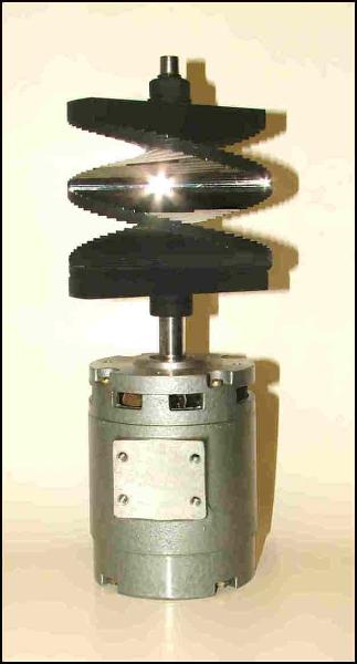
After the successful construction of those two complete sets, I decided I wanted some smaller mirror screws. Within a year, I was able to develop the necessary procedures and special tools, to build a medium size 32-line screw. I later expanded the tooling to include a 60-line model. My mirrors are stainless steel, just like the original ones and I contract with a local machine shop, to cut out the mirrors using a Laser. They also do some very precise preliminary grinding for me on these mirrors. I later decided to build an even smaller set, ¾ size, one that would allow smaller motors to be used. These provide an image size of approximately 3" by 4" inches or 6cm by 8cm. They can usually be mounted directly on a 5/16" diameter motor shaft, as shown below, greatly simplifiying construction. These mirror screws are both available now from Peter Yanczer.
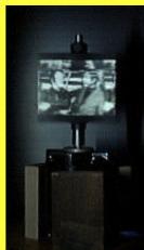
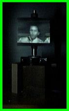
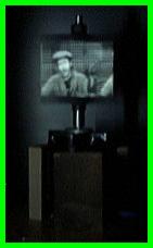
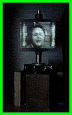
Before I went very much further, I thought that I might set up something simple that would give me a idea of the picture quality I could get with these screws. As I had said before, the easiest mechanical scanner to set up is the mirror screw in this temporary stand shown here below. This one is a 60 line screw and this is the whole scanner. It consists of just the motor and a mirror screw.
|
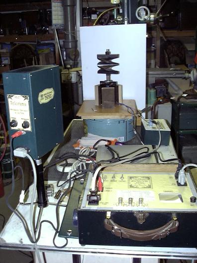
I put together a set up like the one in this photo on the right. The motor is supported by three wood blocks and the motor slips down into them fairly tight. The three blocks are
screwed to a larger board about 12" by 12" board in turn, propped up to get the screw to the proper height for the light source.
There is a white screen behind the screw and to the left is the light source for the screw.
The instrument with the handle is a scan converter that allows me to convert the output of a DVD player to a television format of 60 lines per image and at 20 frames per
second. Another setting on the converter provides a 32 line image at 15 frames per second. |
|
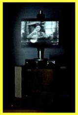
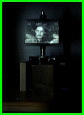
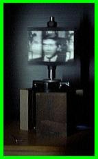
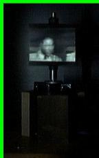
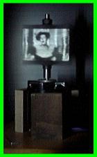
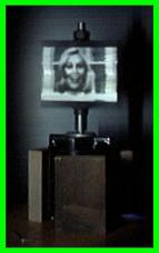
At this time I was using a DVD of a "HEE-HAW" show, which has more than the usual number of close-ups. I used a digital camera with the shutter speeds set to 1/10 to 1/15 of a second and got more good shots than bad. Some are a bit blurry, but keep in mind that they were moving pictures. Also, the picture you see on the screw always looks better than the photographs.
|
|
|
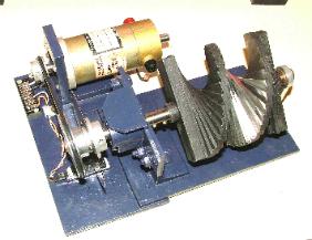
If you are really getting interested, here is an example of a way to set up a mirror screw to provide either horizontal or vertically scanned images. This uses a DC motor to drive the mirror screw through a rubber belt. The belt also rotates a disk with 32 evenly spaced holes, the same number as the mirrors on the screw. The holes are detected as the disk rotates by a LED/Photo diode to provide feedback to the motor drive circuits, in order to keep the mirror screw speed correct and constant. The mirror screw as shown here is supported on a shaft running in ball bearings.
05/25/09 PY
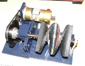
Since this assembly was designed and completed, I have added to it, making it into a complete 32 line mirror screw receiver/monitor.
For starters, I removed the 32 hole synchronizing wheel and replaced the DC drive motor with a 1800 RPM synchronous, 60 Hertz, 120vAC type. In place of the sync wheel and O-ring rubber belt, I installed a 36 tooth Gilmore drive wheel. On the motor shaft I installed an 18 tooth matching drive wheel and a belt, that provided a 2 to 1 speed reduction to the mirror screw. These drive components are as good as gears and run much quieter. The changes will result in a major simplification, while achieving proper synchronization with the camera signal. More about this change-over at another time.
Year 1928 was actually the beginning of the first television boom period. More then a dozen radio stations were either planning to, or were already periodically transmitting television signals, generally late at night at frequencies slightly higher than the broadcast band.
Many of the radio listeners at this time heard their first radio stations on one or more crystal radios, that they had successfully built based on information and drawings shown in their daily newspapers. In the process, they also would have erected good antennas as well as a good ground. Also by 1928, they were likely to have purchased a sensitive radio set, certainly more sensitive than their crystal set.
By this time, radio had really captured the imagination of the public. Many owners were attempting to log as many stations as the could. First by radio, followed by letter or postcard. Because of the nature of signal frequencies in the broadcast band, the strength of the received signals are much greater at night and even more so at the high end of the band. As a result, those looking for new stations to receive spent most of their radio time after dark, at the high end of the broadcast band.
Some radio stations, seeing potential new business with television, began to look for ways to get involved without creating interference with the existing services. They could do this with a simple temporary change in the transmitter. With the change in place, instead of a microphone input to the transmitter, now it would be from a photocell associated with some sort of image scanner.
As for the listeners tuning in new stations at the top of the band, instead of voices or music, they instead heard loud unsteady buzzing, squealing or what seemed to be an unusual form of noise. At the same time, the newspapers once again began running regular construction articles, telling the readers what the stations were doing and how one might build something that actually shows pictures. It seemed like magic.
There were some new words to be learned too, such as Nipkow scanning disk, synchronizing and flicker. There were a number of magazines dedicated to radio, that were beginning to run regular articles about television matters, including how to build all or part of a receiver. The same magazines were running ads, for various television parts or complete kits, that anyone could put together (or so they said). Just about all of the televisions offered used a Nipkow disk, that generally guarantees that one will have a small dim picture. Typical image size on a Nipkow disk is one to two inches square. Light efficiency is is many times less than 1% and the
approximate ratio between the scanning disk size and the image size works out to be about the same ratio.
In the same year (1928), D. B. Gardner filed a USA patent No.1753697 for a mirror screw scanning apparatus. His scanner offered a viewable image almost as large as the scanner. Also the light efficiency was very high because it is was a helical scanner made up of mirrors. It became known as the mirror screw.
Most of the television pioneers of that time were radio engineers that were also responsible for sending out television signals that could be picked up with an ordinary radio. Names like Sanabria, Jenkins and Baird (of Boston Mass) where among the many who became well known because of frequent stories and articles appearing in magazines and newspapers. Many times, the authors were actually the inventors, describing their inventions.
Sanabria was showing off his interlaced scanning. Jenkins had a wide range of developments including some very clever scanning techniques and Baird had a drum scanner with a quick and easy change to other line formats.They were all using Nipkow disks in one form or other, which was invented in 1884. Nipkow's patents had long ago run out, so there were no royalties to be concerned with...and no lawyers. In general, it seems that in the field of television development, that the inventors for the most part, felt that they could and would invent whatever they needed as they went along. There was always a very strong reluctance to paying royalties
to anyone, for anything. They just wanted to collect them. In later years, RCA was especially noted for this. This might explain why there was no mirror screw activity in the USA at any time, although it is known that in the early 1930's, RCA did have in their development inventory, two 60-line mirror screws.
It appears from here, that the best scanner in 1928 and some years later as well, was the mirror screw! However, no one in the USA picked it up, and only in Europe was there any interest. Franz von Okolicsanyi of Hungary began putting the mirror screw to use and in some ways made significant improvments in its operation. In later years, he claimed that he invented the mirror screw, but neglected to patent it in a timely manner. He was later employed by Tekade of Germany as a high level engineer, with the task of developing a low cost mechanical television for the home.
|

All rights reserved. |
|