|
Television Experimenters.com
Mirror Screw - Scanning Engines
 |
MIRROR
SCREW
Scanning
Engines
Its really
easy to build
a Mirror
Screw set
with one of
these! |
 |
What are these scanning engines? by Peter Yanczer
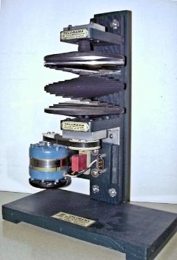
They are a complete mechanical scanning system, using a large stainless steel mirror screw as the scanning element. The screw is coupled to and driven by a synchronous motor of suitable size and characteristics. These
scanners will provide a television image measuring appromately 4.5" by 6.0".
The motor operates on 120 volts AC, 60 Hz. The television image format choices are 30 or 32 lines, horizontal (or vertical), scanned at 15 frames per second. The original format used in Germany in 1930 was 30 lines, horizontally scanned. The 32 line scanner conforms to the very popular, existing "Narrow Band Television" format of 32 lines, either vertical or horizontally scanned. The entire assembly is attached and supported on a wood base. A suitable cabinet can be fashioned, using at least three sides and a top, with the existing wood base becoming the bottom. SO... What do you do with it? And why? |
|

|
OK... But first a bit of history. Television as we know it today, dates back to the nineteen twenties. Television for the most part was being accomplished mechanically and usually somewhere in the mix, there would be something called a Nipkow scanning disk. It could provide real television pictures, however they were small, usually postage stamp size. Image brightness was low too. There was not much one could say for it that was positive. Except that it was still fascinating ... magical, maybe even a little spooky. It might been difficult for Gardner to get the pictures registered on the first ever patent, on a new and unusual method of helical scanning with mirrors. His original scanner was made out of glass plates, but later other materials were tried with stainless steel found to be the most suitable. Briefly, what his helical scanner offered besides potentially a lower cost, was brighter and larger pictures. Due to its shape, it soon became known as a mirror screw.In spite of it being an American development and most likely would have been available to anyone showing an interest, the interest actually shown in this country was next to none. In the meantime, Hans Hatzinger of Hungary and Franz von Okolicsanyi of Germany were each engaged in similar and independent development of mirror screws. Both were granted patents in their respective countries, but on later dates than Gardner. Okolicsanyi became employed as the chief engineer with TeKaDe, a large electronics manufacturer in Germany, where he continued his development work on the mirror screw. As the work continued, the mirror screw was steadily proving to be superior all other types of scanners, including cathode ray types. It was going so well, that the TeKaDe company serious considered stopping all work on cathode ray development and transferring all money and personnel to further mirror screw product development. And this was the ongoing situation until 1935-36.
|
|
By this time, the television scanning rates had climbed to 240 lines and Germany was about to jump to 441 lines. In the mean time, the cathode ray tube had been further improved to the point where for new designs, it had
finally become the scanner of choice, then as well as in the future. Wisely but with some regret, TeKaDe closed their activities on mirror screw set designs and converted to cathode ray equipped receivers, same as the others. Since they had continued their cathode ray receiver development, in parallel to their other work, they were able to make the transition with little difficulty. |
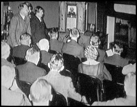
From this information, one may surmise that the mirror screw saw very little actual use. That is true, because the German television market as a whole was very, very small. Its been been estimated that only about 600 sets existed in all of Germany. The average German citizen from 1930 through the middle 1930s, had very little money and at most, could only afford the simplest of radio receivers, much less a television receiver. The government was setting up "television parlors" which were simply a room with one or two television sets and 25 to 40 chairs, for the people to sit. A single post office employee was there to seat the people and adjust the television if need be. There were about three of these parlors set up in Berlin in 1935. The picture here on the left shows one of
the actual television parlors. Television broadcasts were running about three times a week. Only the important people, such as politicians and high ranking officers actually had a television receiver in their homes.
The countries with larger markets in the early years, were mainly England and America. An interesting observation about these countries, is that all of their television manufacturing capabilities were controlled by people who invented television. Or at least parts of it.
For example, John Logie Baird of Scotland, was certainly a gifted man. Every move made by Baird Company in the early years was at his direction. He was known as "the kingpin of the organization, the man with all the ideas."
In America, there was a fairly large television market too. Charles Jenkins was a major inventor of television related devices. He manufactured television studio equipment and a full gamut of mechanical television receiving sets. Ulises Sanabria was also an important inventor/manufacturer.
A question that might come to mind is: Did those people know about the mirror screws. The probable answer is yes! And if that is the case, why didn't one or more of them incorporate the mirror screw into one of their designs?
What are the likely answers? The first might be that it wasn't far enough along in development, therefore did not show enough promise at that time. Someone else's answer might be, that it was too different from what they were setup to do at their factory and there would be too many new things to learn and do. At the end of both answers, they might also add: "Besides, I have a better idea!"
However, the one correct answer is likely to be: "Someone else invented it!" It seems that in many manufacturing areas, there is a situation commonly referred to as "the N-I-H factor". Which means, Not Invented Here. It has to do with royalty payments, licensing agreements and lawyer costs.
Whatever the reason, this fact remains. Mirror screws are very rare and original sets that used them are even more rare. Like maybe nonexistent...
So now, for the question... What do you do with it? And why?
First, I assume some of you are radio/television collectors or maybe just downright fascinated by television. Not so much the programming or commercials (Ha, Ha), but instead the devices, the mechanisms, the apparatus, that makes it possible to show the pictures in our homes. If you fall in one or more of these categories, I would expect you to be interested in mirror screws. To what extent, I can't say. But I can say this, about that. It is a rare device, whether it be original or not. It has an interesting history, with much of it, yet to be discovered. It also shows really well in demonstrations, creating a genuine excitement amongst those that see it. That is to say, that it has an excellent "WOW Factor".
So, the answer to the question of what do you do with it, for me is... To show it off... and that is enough for me. For others, with one of these scanning engines and a few wood panels, you can make a cabinet. Look at the one below. Simple enough? Huh?
|
The electronics and light source are straight forward and relatively easy to accomplish. With a little effort, you can
have a set, a really special set. WOW, collectable!
The electronics and light source are straight forward and relatively easy to accomplish. With a little effort, you can
have a set, a really special set. WOW, now you are talking about a real collectable!
Recently, I have started building some 4 inch 32 and 60 line mirror screws to sell. |
|
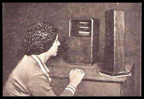
Shortly after receiving this photo of this supposedly French mirror screw set, I thought I might build something similar. Since this photo is the only reference I have on this set, I needed to extract as much information from this photo as I could. I feel safe in saying that the following is true: It would appear that it is a two piece set, the first being made up of a cabinet containing the mirror screw and the drive motor for it. The second piece contains the mirror screw light source and possibly a small portion of the necessary lectronics. Although only two pieces are shown in the photo, I believe that somewhere there is actually a third piece or cabinet, containing the
electronics for the light source, power supplies and a radio receiver, for picking up the television signal.
Due to the size of component parts used in the 1930's, it is highly unlikely that all of the necessary electrical components to operate the mirror screw lamp, could fit into the one cabinet with along with the light source. Hence, the need for the unseen third cabinet.
This set was to be bit smaller than the mirror screw sets I had built before, so it would require a totally new mirror screw too. After thinking about this for a time, I decided to go ahead and build this new set and to use a new 60 line line mirror screw with it. The 60 line format in the early 1930's was in fact the first "high definition" television format of the day providing a better looking picture in all respects. Therefore, I felt that this was the way for me to go.
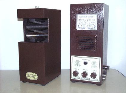
So, here is what I have built. It's all done, looks good and it works great! And by way, it is available. |
|
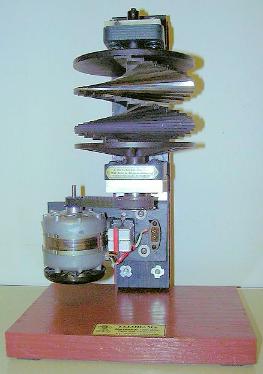
This set is close to the same physical size as the orignal and will produce a 3" X 4" image.The cabinets contain three main
items. In the one on the left: a 1200 RPM synchronous motor, with a 5 ufd, 360 v, phasing capacitor for the motor and the
mirror screw. Of course, there is the cabinet itself, a 3 pin connector for a 3 ft. cable to the other cabinet, plus the usual, hardware, rubber feet and etc. This whole package weighs 10 pounds and in most respects, is very similar to the original set. |
Except for similar size, the second piece, shown here on the right, contains all of the electronics, except for the radio receiver. This set gets its signal input from either a mechanical 60 line camera, or a scan converter. AC power in inputted to this cabinet and a three wire cable supplies power from here to the other cabinet for the synchronous motor. The main switch and all of the controls are on this cabinet.
It also contains a complete sound channel, including the speaker, which is totally absent in the original set. This cabinet also contains the amplifiers for both sound and video, plus the necessary power supplies and the light source for the mirror screw. There are no vacuum tubes used in this design. Instead, transistors and integrated circuits serve in all of the necessary functions. Circuit designs reflect a 1980's era. This part of the set weighs 5 pounds. It has been demonstrated to large groups, very successfully, three times and it shows very well. It is for sale and if you are interested, Email me.
As to the question of "why" I do this. It's because I do enjoy doing it and I believe it contributes to ones physical and mental health.
If you are just getting interested too...get in touch and keep in touch. |

All rights reserved. |
|
