|
Television Experimenters.com
Quick & Easy Mirror Screw Lite Source
Mirror Screw - Simple Lite Source by Peter Yanczer
I'm going to try something different here. This is a construction article for use with a light source for the mirror screw.This will describe one of the earliest ones I built over 10 years ago. It was one of very simple all aluminum construction,that would work just as well if made entirely of wood. It went together very quickly and works just great. If you have the tools and skills to work with metals, I'd say that this is the way to go. If you should decide to go with wood, it will take a little longer to build, because of having to stop work while some of your glue work dries, before you can continue on. One dimension that needs special mention is the "lite stop gap". For the 32-line screws, it should be 3/32". For the 60-line screws, it will be 3/64".
|
Here is the drawing:
Basically, all you have here is a wood or metal container, in which there is located a length of clear 1/2" diameter acrylic rod, which acts as a lens and and 27 LEDs in a line, all pointed at "lite stop gap". In this case, I used cable connectors of computer drive cables, as sockets for the LEDs and it worked out pretty well. I also mounted a small section of "vector board", on which I supported nine 1/4 watt, 33 ohm resistors,
The rod is drilled and tapped on both ends and is mounted with two 1/2" long screws. The wiring terminates into a common RCA female phono connector. The wiring consists of nine parallel groups of three series connected LEDs, each with a 33 ohm, 1/4 watt resistor. The LEDs and the acrylic rod are located on an imaginary centerline in the case. The mounting hole will fit most tripods. |
|
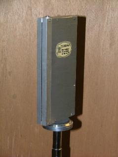 |
Here are the pictures:
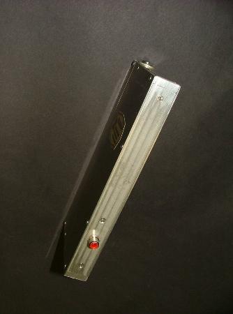
It is shown here mounted on a tripod. This is the way it might be normally used. Note, the circular part at the bottom is a part of the tripod. You might notice here that the part nearest you is actually a length of aluminum angle. There is a similar piece opposite it, those gap".
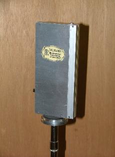
Here on the right is a picture of it turned the other way:
The covers on this side and the other side are just about the same. |
|
|
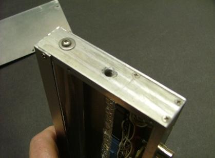 |
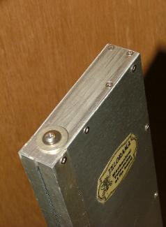
This is a view of the top surface. The 6X32 screw supports the acrylic rod. All of the other screws in this view are size 2X56.
|
|
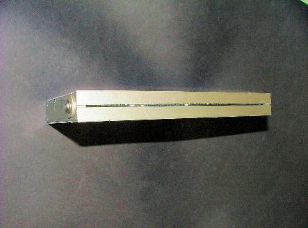
This view is looking at the front of the
lite source. The top is at the right in this picture. This gap is the smaller
measuring measures 3/64th. |
Here on the right is the rear surface of this light source.
The RCA connector is near the bottom, but its location is
not critical |
|
|
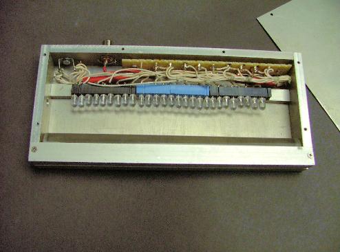
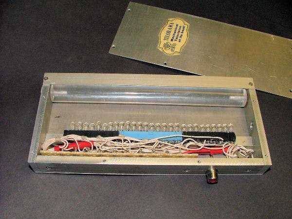
Here is a view of the internals.
The vector board contains the
terminals to support them. The
Here is a view of the internals.
Sockets are held in place by an
The vector board contains the
The vector board contains the
nine resistors and suitable nine
resistors and suitable terminals
to support them. The sockets are
held in place by an epoxy cement,
in this case, on an aluminum bar.
Wood would do just fine in place
of the metal. In this view, the
bottom is to the left and you can
see the hole for the tripod. The
angle pieces at the front are still
in place and for he most part,
hide the acrylic rod from view. |
At this time, with a few volts powering the LEDs, the acrylic rod can be rotated a bit, as it can have an effect
on the eveness of illumination on the screw, Also, the LEDs may need some minor adjustment in the sockets,
again to try to improve on the eveness of the light falling on the screw. A sheet of white paper about a foot
away can be used to help evaluate the situation.
GOOD LUCK! |

All rights reserved. |
|
