Early Electronic Television
ATC Kinet Technical InformationThe Kinet gets its sweep and video signals come from the a "master" receiver. The CRTThe CRT is 5 inches in diameter, and the opening at the top of the set is 8 inches in diameter, for a magnifying lens. The mystery is what CRT is used. The dimensions suggest that it was a 5BP4. However, the socket is 8 pin, while the 5BP4 uses a 11 pin socket. I have a table which lists CRTs available in 1939 but none of the tubes listed there seem to apply. It is possible for a tube to have only 8 connections if two of the deflection plates are tied together, as some of the tubes listed in the table do. Chuck Azzalina sent me a data sheet for a National Union 2005 "Videotron", made in 1938. This tube has a 8 pin base, and is the right size to fit the Kinet. Finding this tube will be almost impossible, so we will probably put an 8 pin base on a 5BP4, which very similar to the 2005. A 6.3 volt filament transformer will be needed since the 2005 has a 2.5 volt filament and the 5BP4 has a 6.3 volt filament.
The location of the CRT face and lens
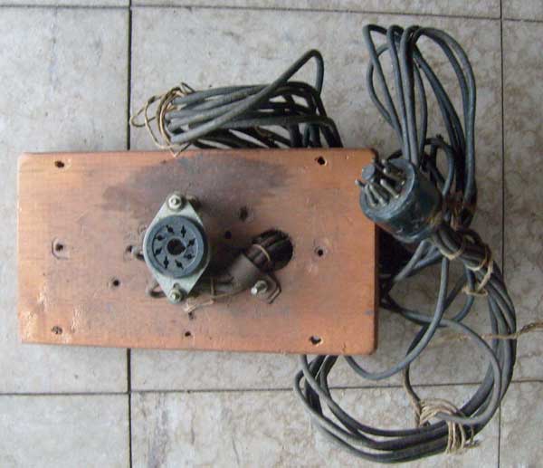
The CRT socket and cable
The CRT housing, showing the location of the CRT socket, CRT, and lens
The Chassis
The Camera and Support EquipmentVideo, horizontal sweep and vertical sweep are supplied to the Kinet, most likely through coaxial cables, from ATC's picture signal generator.> The video is delivered at a level suitable to drive the CRT directly, as shown in this diagram:
|