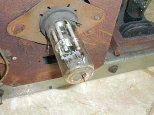
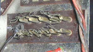
The jack to select CRT current (bottom view).
Each loop has a few ohms resistance.
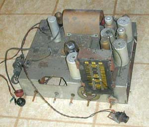
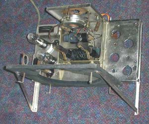
The TV chassis, after reassembly. The brass RF module will be mounted
on the right side
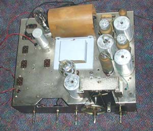
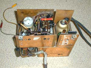
The RF module as viewed from the top.
The second RF amplifier tube (valve) is visible in the center. On the left
is the socket for the first RF amplifier,
and on the right is the socket
for the video amplifier. The red plug
goes to the input of the sync amplifier,while the yellow plug goes to the CRT
cathode.
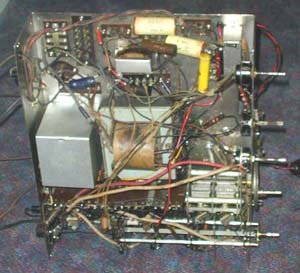
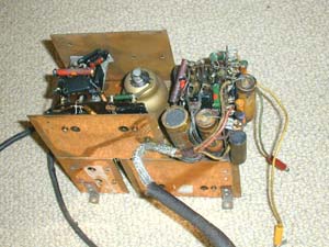
In the bottom view the first RF amplifier is visible on the right. On
the left is the video amplifier. At the front left the diode detector
is barely visible. In front is the power cable (shielded). On the
right are the antenna input cable and the cable that connects to the
41.5 mHz input on the radio chassis.