Early Television  
Mechanical TV History How it Works Mechanical Sets at the Museum Gallery Database Summary Broadcasting Technical Inforation Restoration Advertising Articles Roger DuPouy's Site Peter Yanczer's Site Gerolf Poetschke's Site Eckhard Etzold's Site
Early Electronic Television History American Sets at the Museum British Sets at the Museum Gallery Database Summary Broadcasting CRTs Accessories Technical Information Restoration Advertising Articles Gerolf Poetschke's Site Eckhard Etzold's Site
Postwar American TV History American Sets at the Museum British/Europen TV History British/Europen Sets at the Museum TV in the Rest of the World Gallery of Unusual Sets Broadcasting CRTs Accessories Technical Information Restoration Advertising Articles Eckhard Etzold's Site
Early Color TV History Sets at the Museum Gallery Database Summary Broadcasting CRTs Accessories Technical Information Restoration Advertising Articles Pete Deksnis's Site Ed Reitan's Color Television History Eckhard Etzold's Site
The Early Television Foundation About the Museum Directions to the Museum Articles about the Museum Support the Museum Join our Email List Our Newsletter - "What's New in Old TVs" Equipment Donations Museum Members and Supporters Members Only Monthly Online Meetings Annual Convention Swapmeets
What's New on the Site Classifieds Parts for Sale Resources North American Radio and TV Museums Search the Site
Contact Us Facebook YouTube Channel

Postwar Television

Portable Sync Generator

Early Television

Click here for high definition photo

Early Television

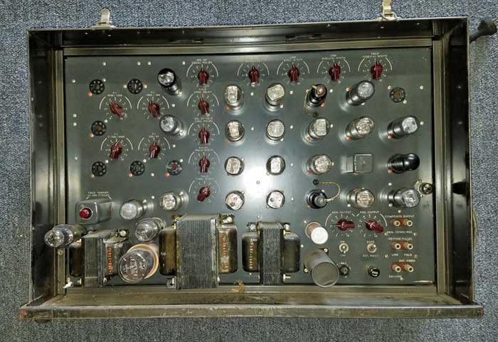
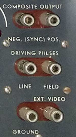
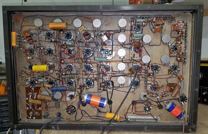
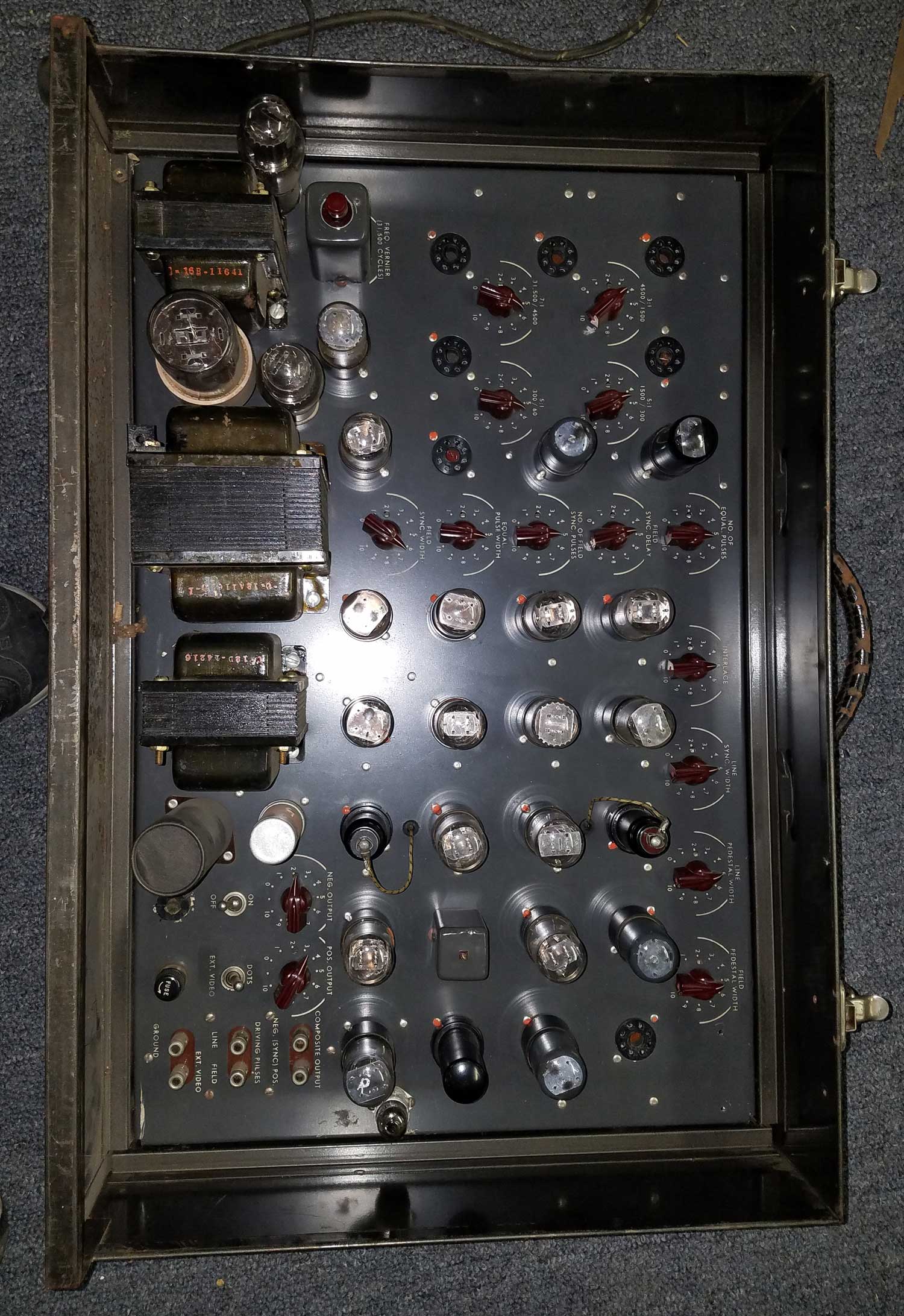
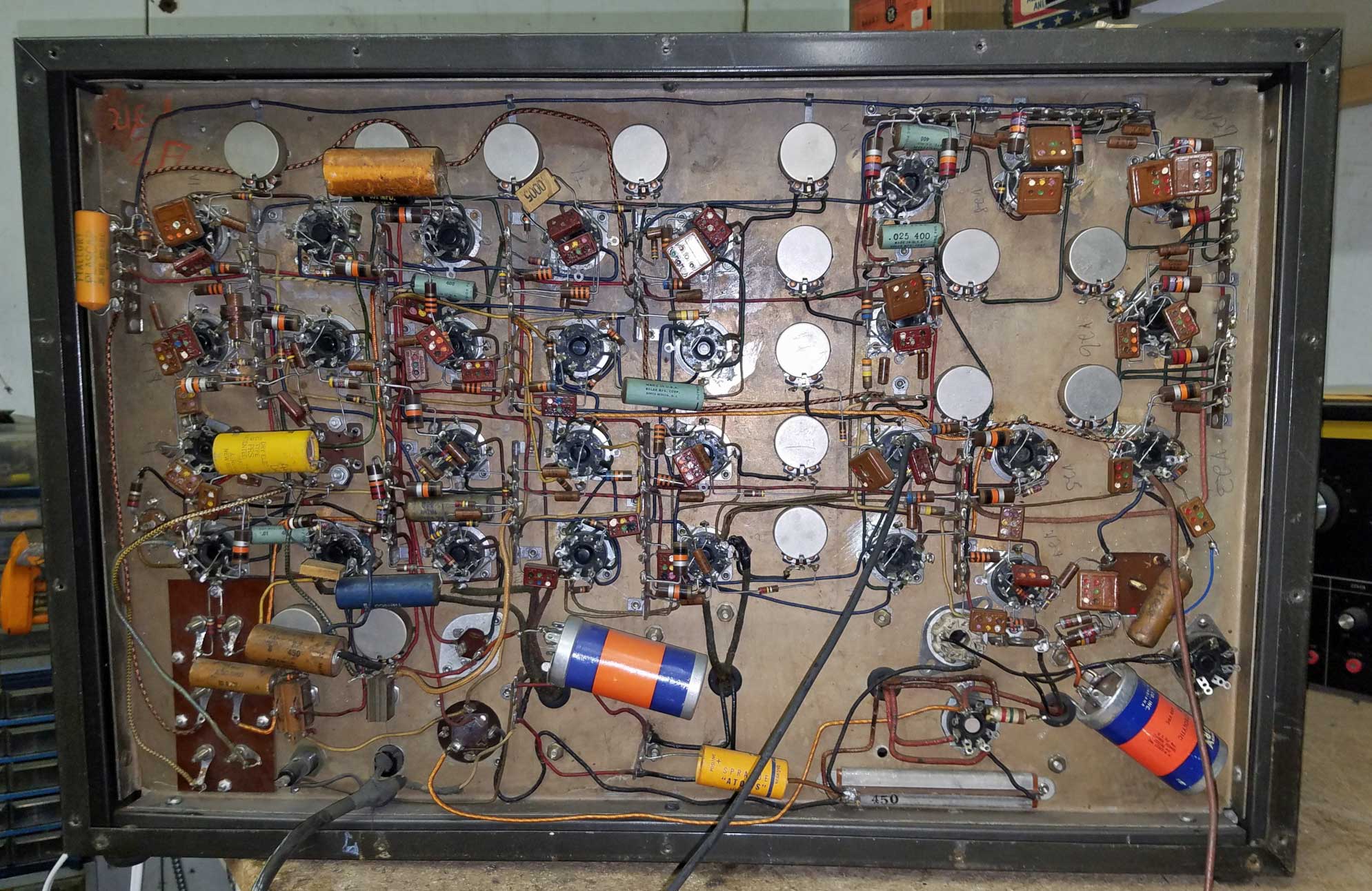
The outputs

This device has no manufacturer identification, but it appears to be a production unit, with components riveted in place. In addition to the outputs shown below, it has two test leads coming out the rear of the cabinet. It was donated to the museum by the National Capitol Radio and Television Museum and was apparently used by ABC or CBS in New York.

I inserted the missing 6SN7s and powered it up using a variac. Amazingly, none of the electrolytics got hot. By replacing a few parts I've been able to get most of the unit working. It generates sync, blanking, and drive signals. The output is a composite video signal with either a dot pattern or video from an external source (camera).

Here are comments from George Lemaster:

I briefly looked at this one at the convention, and it does not look like anything I've seen before. It has to be 40's, maybe early 50's vintage.

I've never seen a broadcast sync gen that didn't have UHF connectors for coax cable, until the late 60's when some vendors started putting BNC's on them. So the binding post output thing is really odd.

All the post war, 1940's equipment I've worked with like the RCA TG-1, had UHF connectors and standard -4 volt pulses. 

At one time I worked for an engineer who started at RCA Camden in 1938. He told me the zero to minus 4  volt for all pulses was the cutoff for a 6SN7 and that was the reason for the 'standard'.  I believe that voltage level holds today on all sync gens.

He also said the TG-1 was designed pre-war and modified to 525 line when the standard changed. I never saw a 441 line generator, but he TG-1 had UHF's.

Clearly commercial construction, but they did some things I thought odd, like mounting the frequency control oscillator near the heat of the power supply.

The arrangement of the counters and controls for them is different than any other I've seen. RCA used 'stairstep' counters in tube and early transistor units. Looking at he controls, this may use the same counter method but has a lot of knobs I haven't seen.
Other vacuum tube sync gens like GE and TEL-INSTRUMENT used a delay line with flip flops for pulse timing.

I've worked on DAGE tube sync gens, which were not great but didn't look like this.

My guess is it was not used by a network broadcaster, but was some portable industrial system.

I believe that George may be correct. The unit contains a sync generator and a dot pattern generator. It has horizontal and vertical drive outputs that could feed a camera. It also has a composite video input. All of the inputs and outputs are high impedance and I suspect that connections were made to a camera control unit. The test lead that come out the back are connected to the 31.5 kHz oscillator, probably to allow setup of its frequency.

The unit is clearly late 40s, using 6SN7s and 6K7s. That predates vidicon cameras, which were introduced in the early to mid 50s, so the unit was designed to work with an IO or Iconoscope camera. I haven't seen any mention of industrial TV systems from that era, so suspect that this was for use in broadcast television. I know that there were small manufacturers of IO cameras after the war - I worked on one in the mid 50s, but I can't remember the name of the company.

Early Television

Click here for high definition photo


Early Television Museum
5396 Franklin St., Hilliard, OH 43026
(614) 771-0510
info@earlytelevision.org