
|
Vintage Television Sets and Colour Television Sets from the Dawn of Television until Now
Echard Etzold's Site |
|
Early Television:
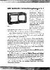
Documentation: Deutscher Fernseheinheitsempfänger E 1 "Telefunken"
1939
Click photo for enlargement!
![[Text in deutsch]](Images/flag_de.jpg)
|
|
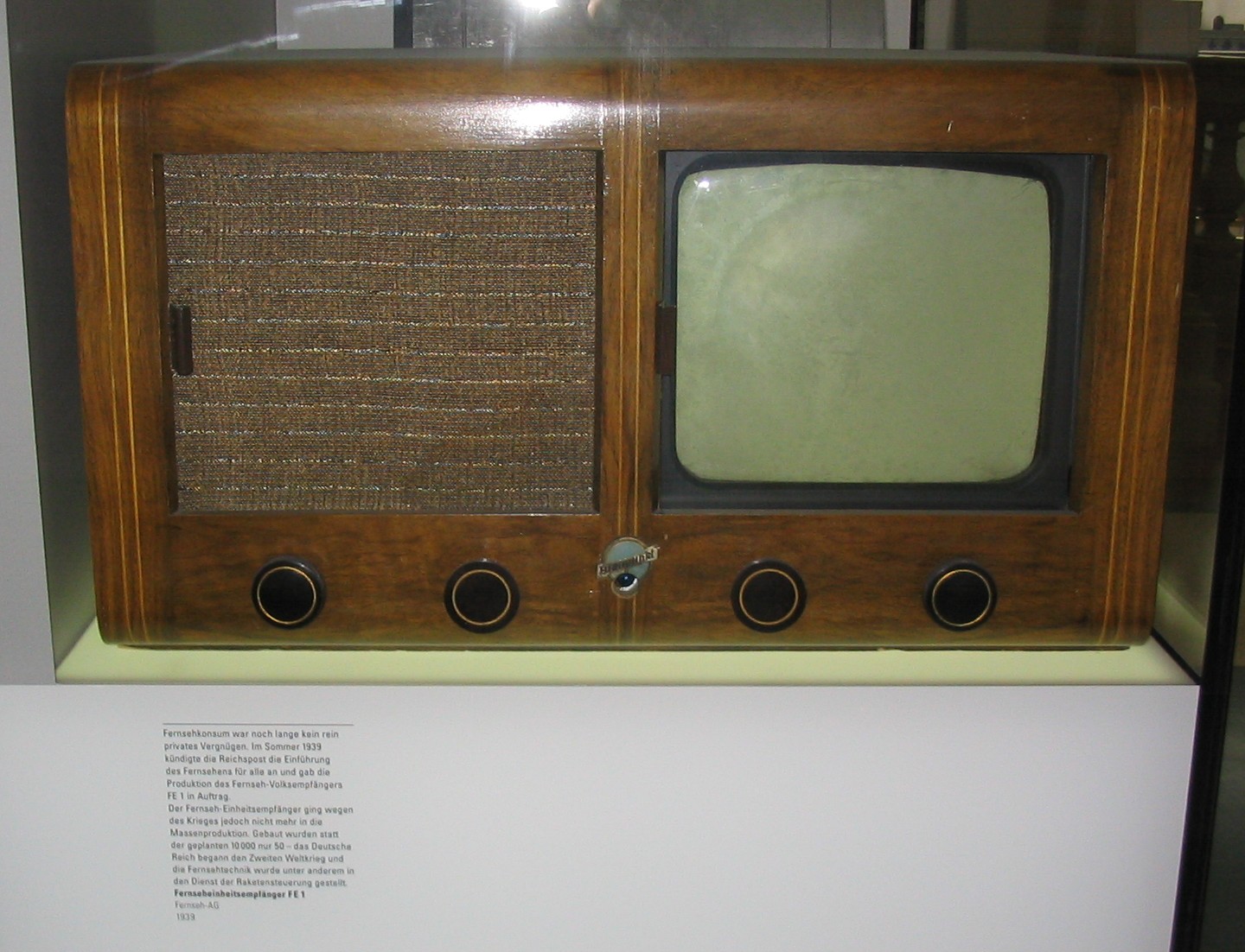
The German Einheitsempfanger E 1 was a joint development of the German
industry under the leadership of the research institute of the Deutsche
Reichspost, in order to make an inexpensive television broadcast receiver
available for all social classes. It was celebrated as a big breakthrough
at the radio exhibition "Funkausstellung" in 1939. The retail price was
650 Reichsmark and was thereby only approx. three times what one would
pay for a good superhet radio receiver. (Televisions from previous years
sold for up to 1800 Reichsmark.) Unlike the Volksempfänger VE 301
(German
People's Radio, for which a minimalistic technical concept was the basis,
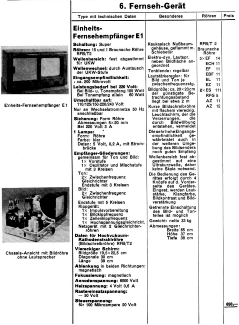
the E1 was of high technical quality. The receiver operates with 110, 125, 150, 220
or 240 volts A.C. main currents and produced a surprisingly
high picture quality, much better than that of other receivers of the time,
and equal to sets made decades later. The first production was to be 10,000
sets and was intended for the Berlin region. The devices were to be distributed
beginning at the end of 1939. But the beginning of World War II in September
1939 stopped the further development and distribution of the E1. Altogether
no more than 50 devices were produced, and only a few survive today. The
German television became history, and only a few people remember the technical
details. Most Germans had to take care to stay alive and were shocked about
the true extent of Nazi terror.
This web page reports one of the very rare, complete, and unmolested
E1. These photos were taken in 2004 before the new owner made considerably changes at the chassis
and the cabinet.
|
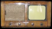
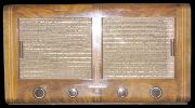
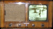
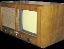
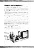
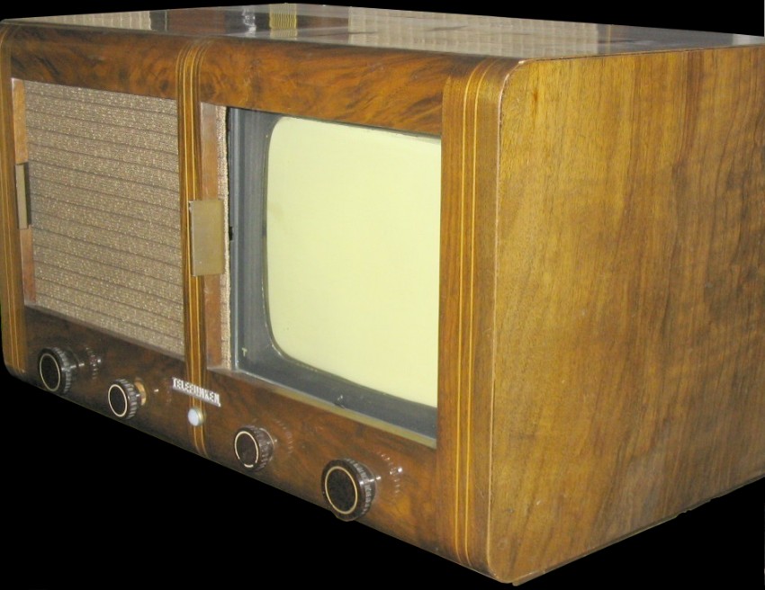
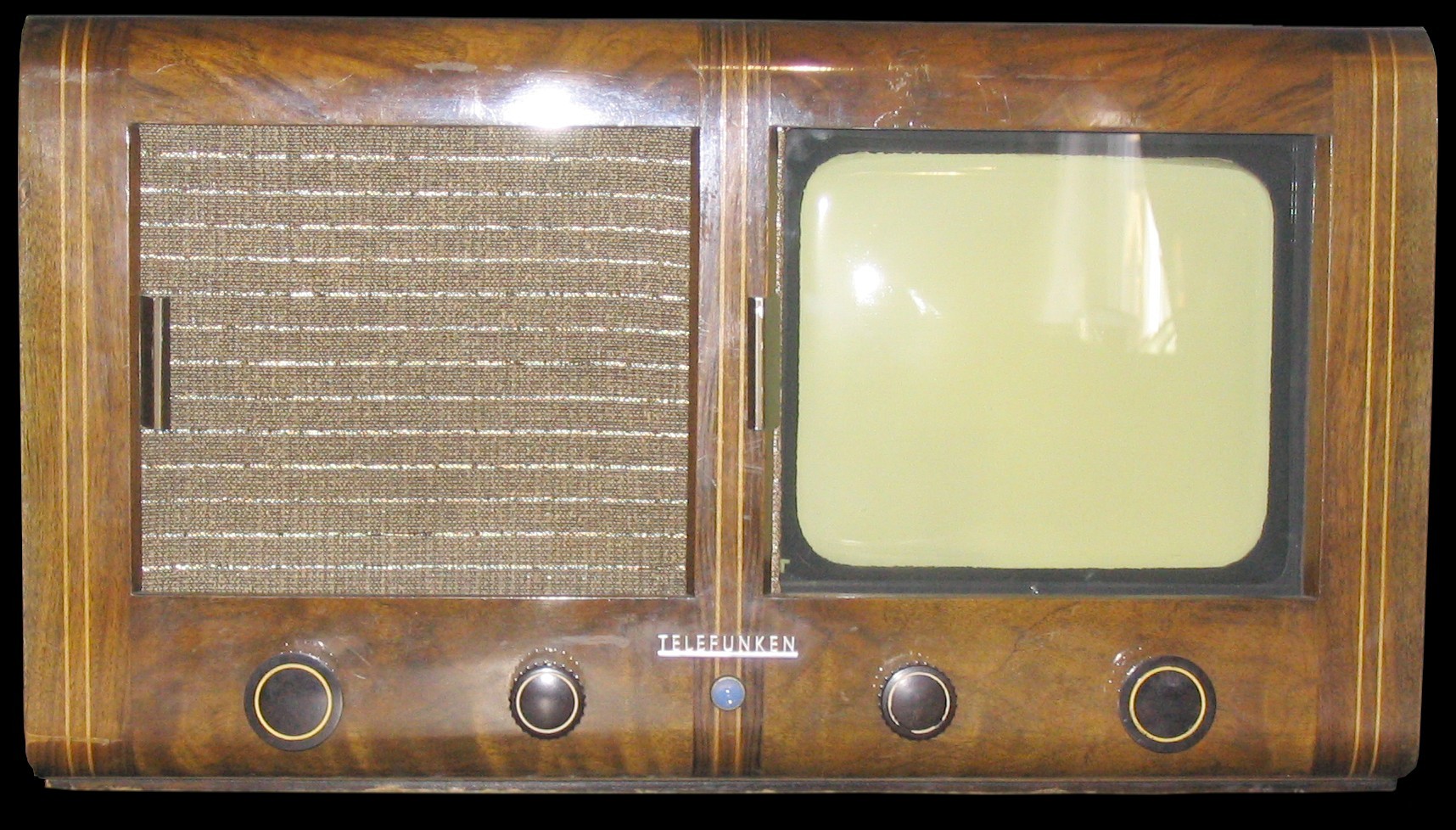
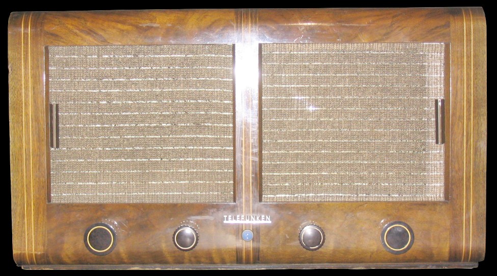
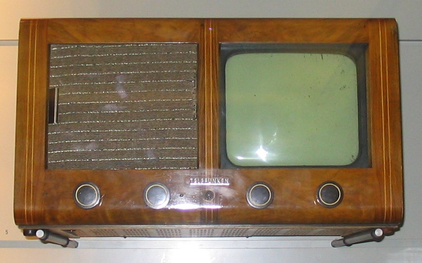
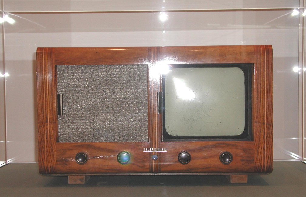
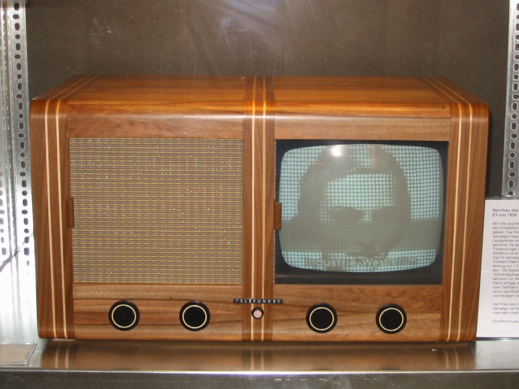
The E 1 possesses a sliding door in front of the picture tube,
with which the screen can be hidden. With the door closed it looks similar to
a contemporary radio. The E 1 was more sophisticated than any other on the world.
It has only 16 tubes (including the picture tube) and consumes 185 watts. When
used for audio reception only it consumes only 60 watts (a comparable American
set, the Philco mirror in lid set made in 1938, consumes more than 250 Watts
and needs 22 tubes). The picture IF frequency is 8.4 mHz and the audio IF is
5.6 mHz. The video bandwidth is 2 mHz and the distance between picture and audio
carrier 2.8 mHz. The horizontal (line) frequency is 11.025 kHz and the vertical
(frame) frequency is 50 cycles per second. A frame consists of 441 lines with 25
per second, using interlaced scanning. The set was internally adjusted to receive
a single VHF channel in the 40 to 50 mHz range. The E1 was manufactured by the
companies Fernseh A.G., Radio A.G. D. S. Loewe, Lorenz A.G., Te Ka De and
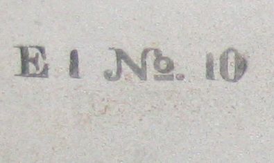
Telefunken. The equipment shown here is a Telefunken receiver, production number 10.
|
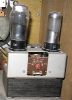
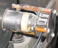
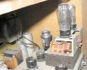
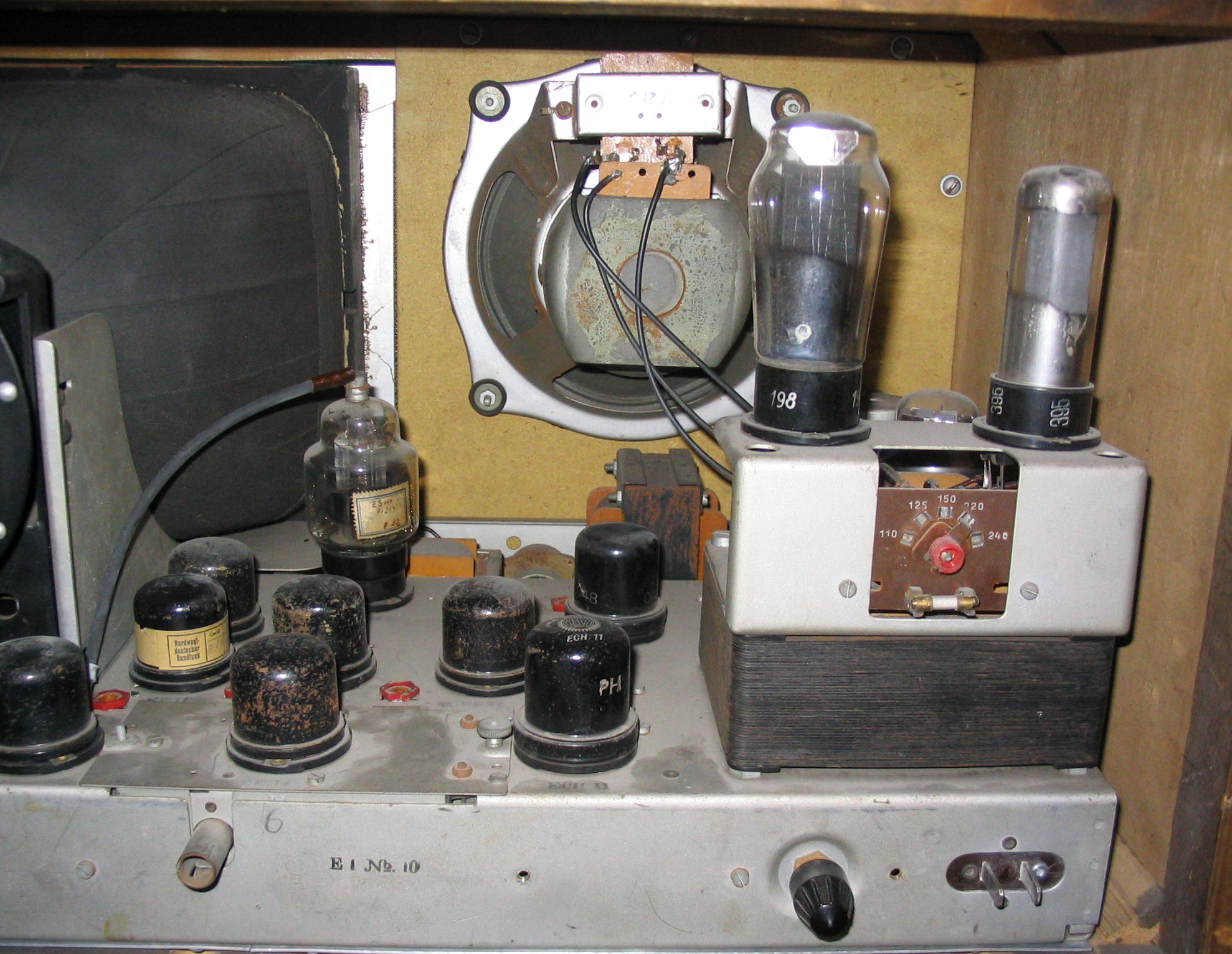
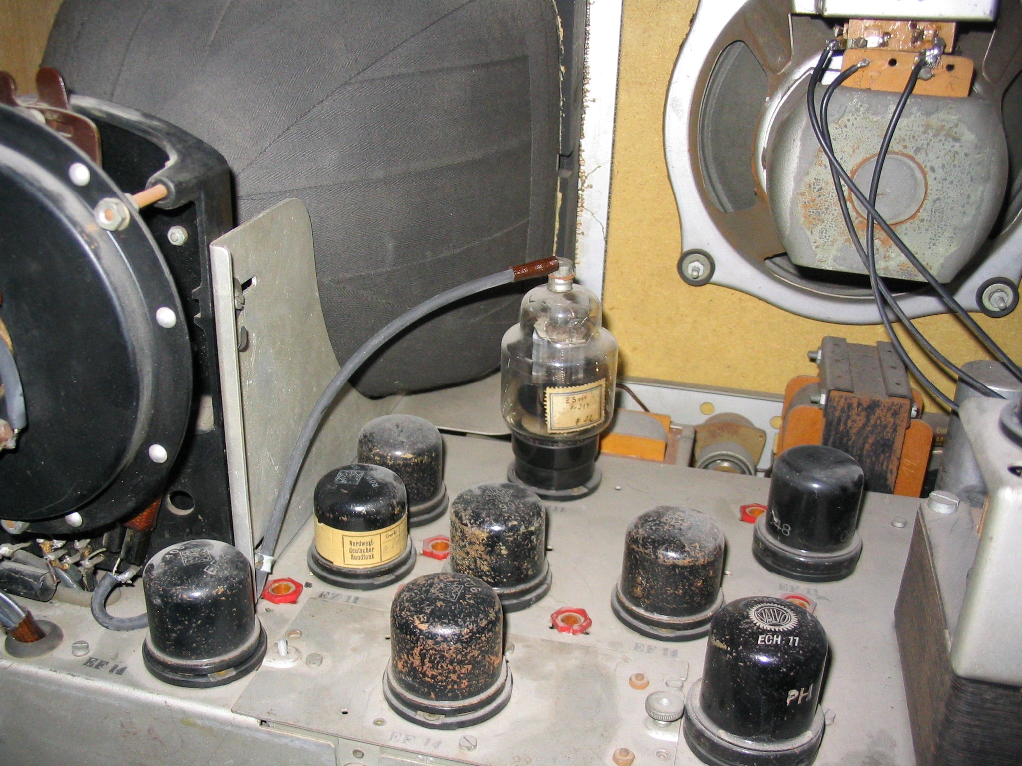
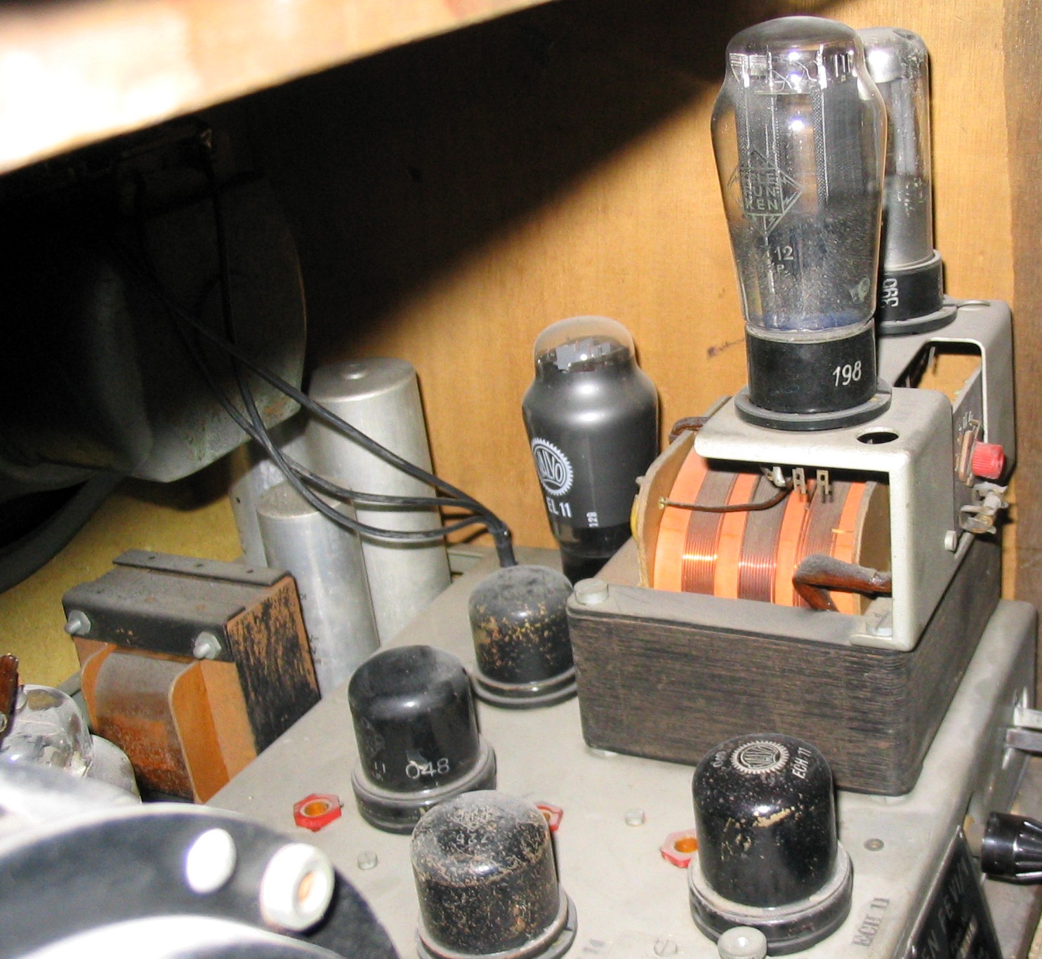
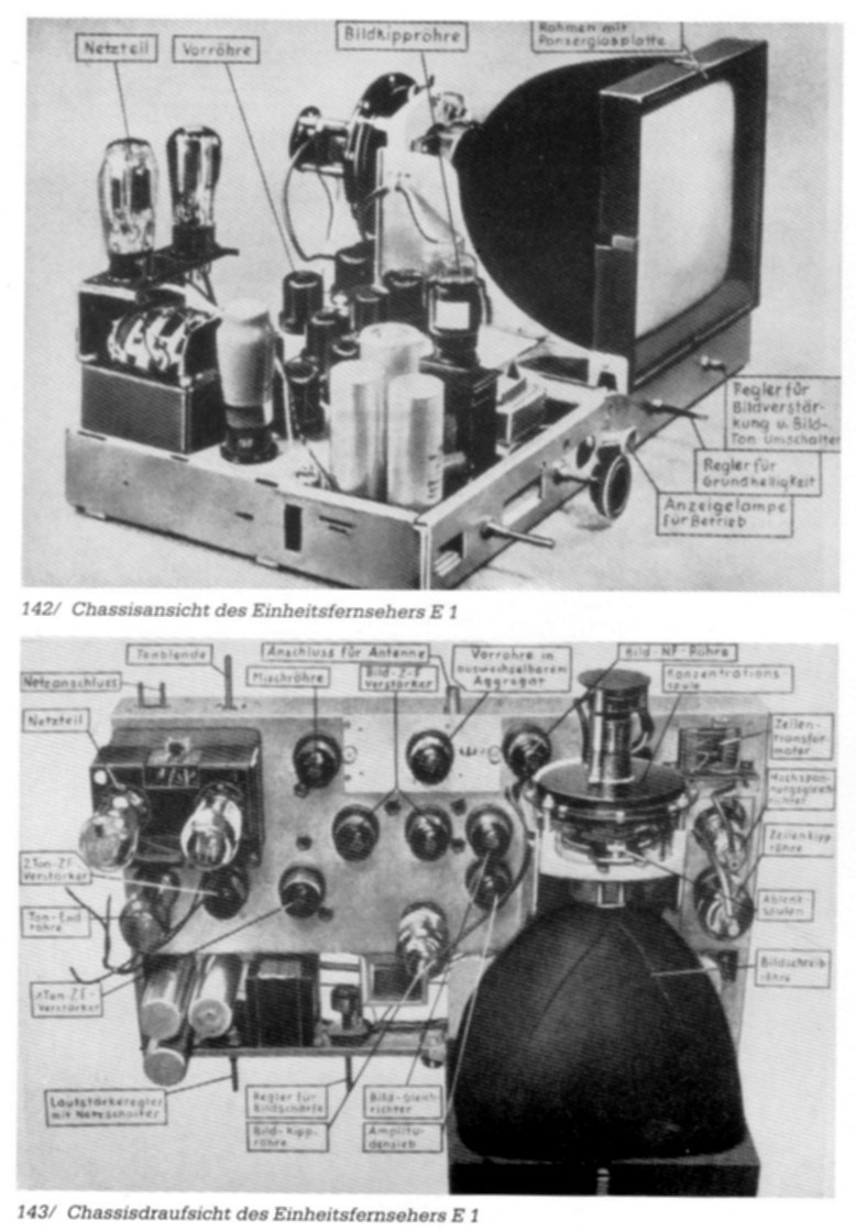
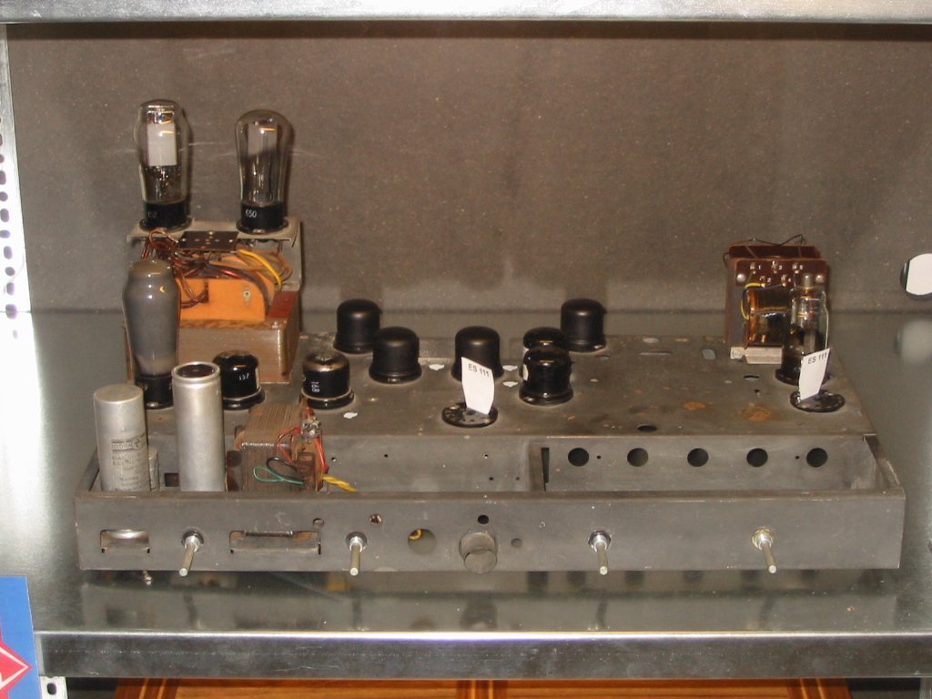
The power pack has two sections. The video, vertical and horizontal deflection
circuits are supplied by a AZ 12 tube, which can be switched off for audio only
reception. (Television programming was only provided a few hours a day. At other
times the local radio programme was transmitted on the television channel.) The
audio receiving circuits are supplied by the AZ 11. The inner circuit currents
are completely separated from the ac power line, therefore the power transformer
was dimensioned much more largely than in later concepts. The industry developed
special tubes for this TV set. In the picture on the right you can see the metal
tubes used in the signal processing circuits.
|
For the VHF tuner, IF circuits and the video output stage the EF 14 was used, a
metal tube. Unlike radio receivers there was no way the user could change the frequency
the set received. It was internally tuned to the local TV transmitter, and only by
replacement of the entire VHF tuner (e.g. removing the receiver from the residence)
was it possible to receive another station. The magazine "Fernsehen und Tonfilm",
number 16, 1939 said: "The oscillatory circuits of the input stage and the
oscillator are firmly co-ordinated, since it is not necessary to be able to receive
several television stations, because current stations and those planned for the near
future are relatively far apart." - inconceivable today, when the television
viewer with satellite reception can select hundreds of TV channels. The antenna signal
is amplified by a EF 14, then fed to a ECH 11 oscillator/mixer tube. The separation of
the audio IF and the video IF takes place in the plate circuit of that tube. The video
IF (8.4 mHz) is amplified in a two-stage IF amplifier (EF 14s). An EZ 11 is used as a
full wave video detector. Another EF 14 is used as a video amplifier to bring the video
signal up to 30 Vss. This signal is fed to the Wehnelt cylinder of the picture
tube and provides sufficient contrast.
|
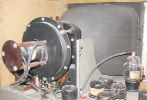
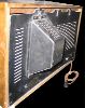
A new and unique development was the rectangular picture tube (or "Bildschreibröhre" =
'picture write tube', as it was still called in the old German documents) with a
flat screen, which exhibited hardly any pincushion distortions. All other prewar CRTs
were round, and even into the middle of the 1950s round tubes with curved screens were
still common. Flat screen sets were not made until the end of the 20th century. The shell
of the tube is covered with Leukoplast in order to protect the equipment inside the cabinet
from implosion. In front of the screen a Sekurit sealing pane was attached, in order to
protect the viewer against fragments from possible implosions. The picture tube operates
with magnetic deflection. For the deflection saw tooth-like currents are used, which produce
an appropriate magnetic field through the deflection coils for deflection of the cathode ray
beam. Focusing also operates magnetically.
|
In the magazine Funkschau, No. 31, 31 July 1939 was written: "The new television receiver
E1 supplies an extraordinarily bright, well contrasted picture of deep sharpness without any
geometric distortions. This is due to the new picture tube, which possesses a rectangular
shell and a flat fluorescent screen, so that the picture does not look like it was 'pulled
over a roller'. In addition the tube is built very short, so that the depth of the receiver
could be minimized. It is smaller than the numerous new Superhets." The picture tube
needs an anode voltage of 6000 V, the dimension of the screen are 19.5 cm x 22.5 cm with
a screen diagonal of 30 cm.
|

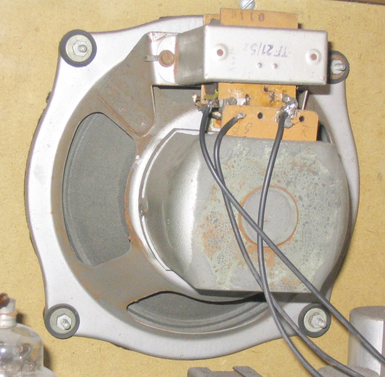
The audio IF of 5.6 mHz is amplified by the pentode EF 11. It possesses an adjustable cathode
resistor, with which the volume can be changed. A EBF 11 is used as the second audio IF
amplifier and detector. The audio signal was amplitude modulated (contrary to today's
frequency modulation). From the EBF 11 the rectified audio signal goes to a EL 11, the
audio output tube, which makes good sound possible with a power of approx. 3 watts. An
output transformer connects to a dynamic loudspeaker. The audio IF bandwidth is 150 kHz,
much greater than the capacity of the loudspeaker reproduction technique at that time.
The wide bandwidth was necessary because of drift in the local oscillator.
|
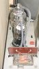
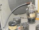
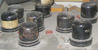
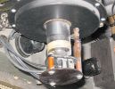
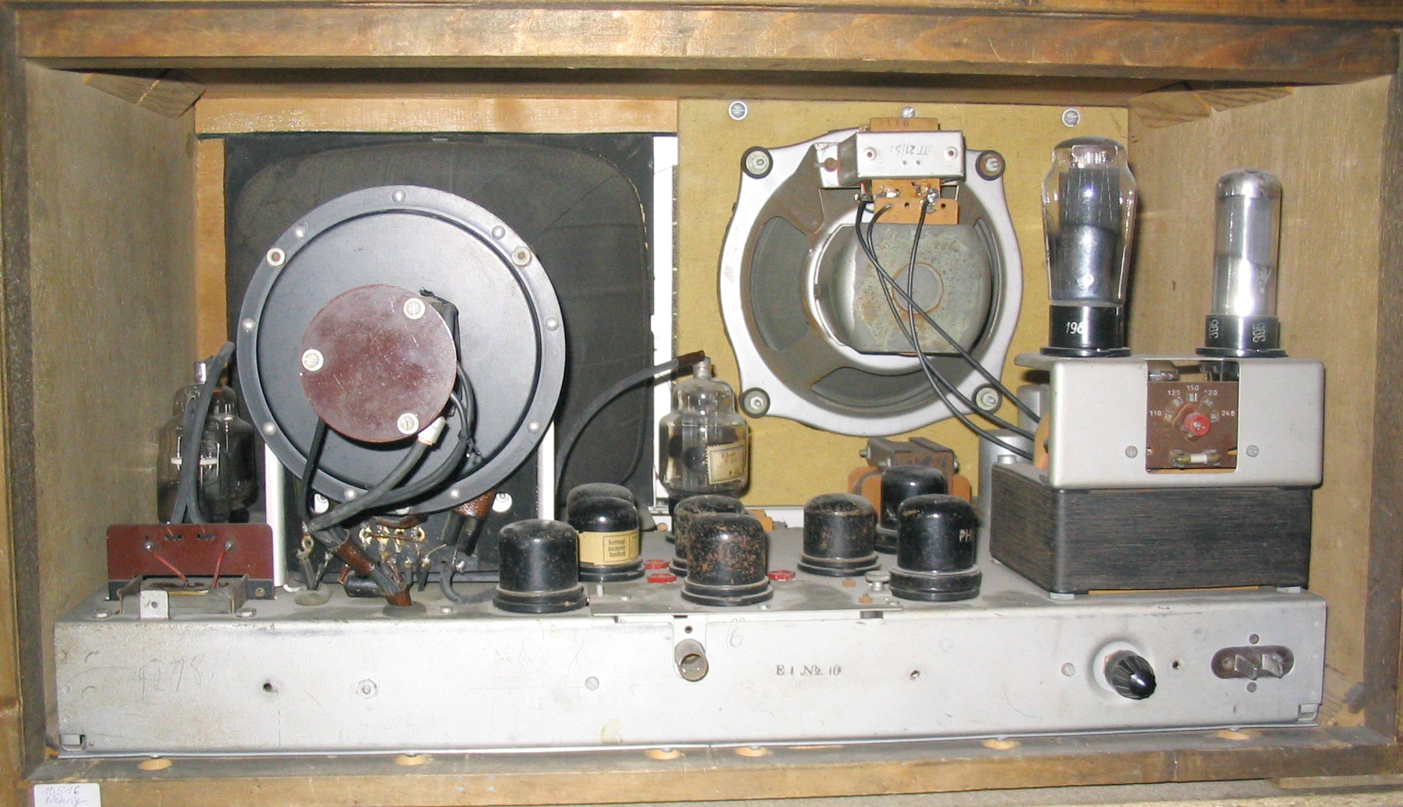
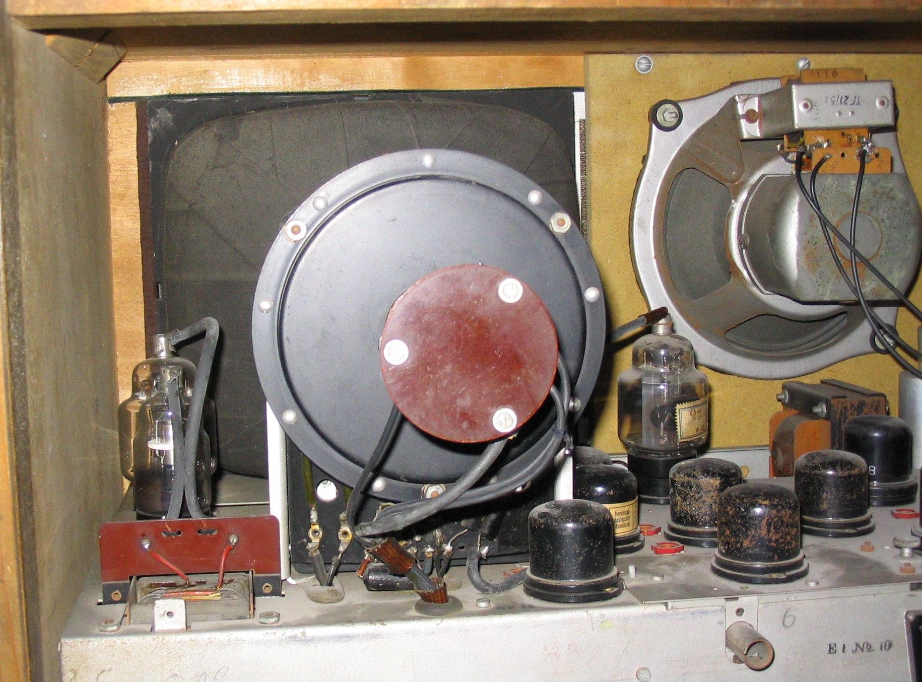
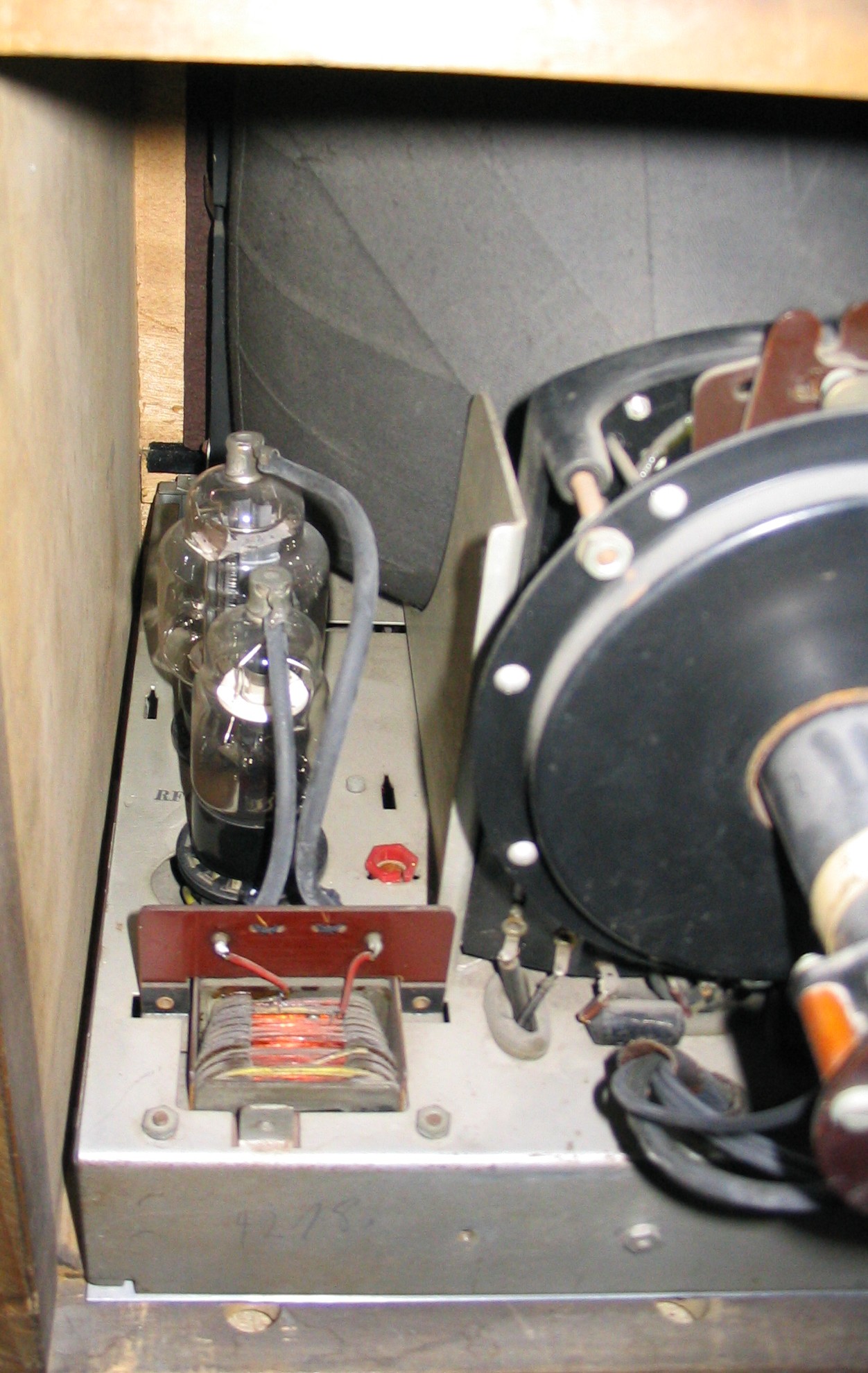
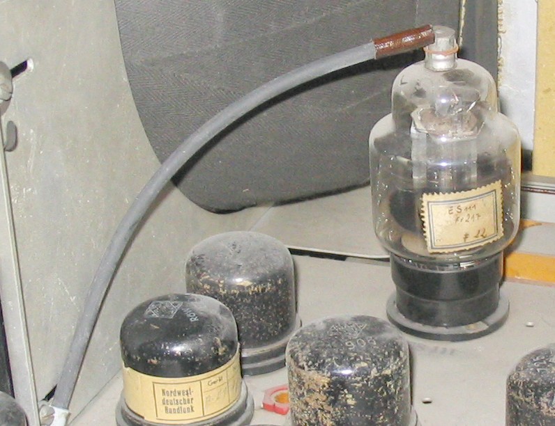
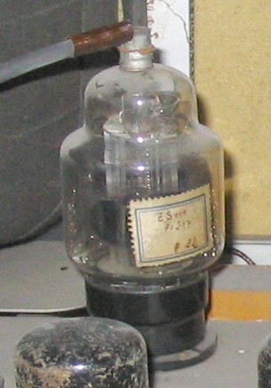
The separation of the synchronizing pulses from the video signal takes place in a EF 14
with two transformers connected to the plate. The vertical (frame) and horizontal (line)
output stages (for both a ES 111 was used) are sawtooth oscillators and amplifiers together
in one tube. The synchronizing pulses are fed to the third grid of the tubes while feedback
and oscillating signal is fed to the control grid. For the first time (like first American
TV sets made before the war) the high voltage for the picture tube was generated by the
flyback impulse of the horizontal (line) output transformer and was rectified in a special
high tension rectifier tube (RFG 5). This solution was much better than a separate expensive
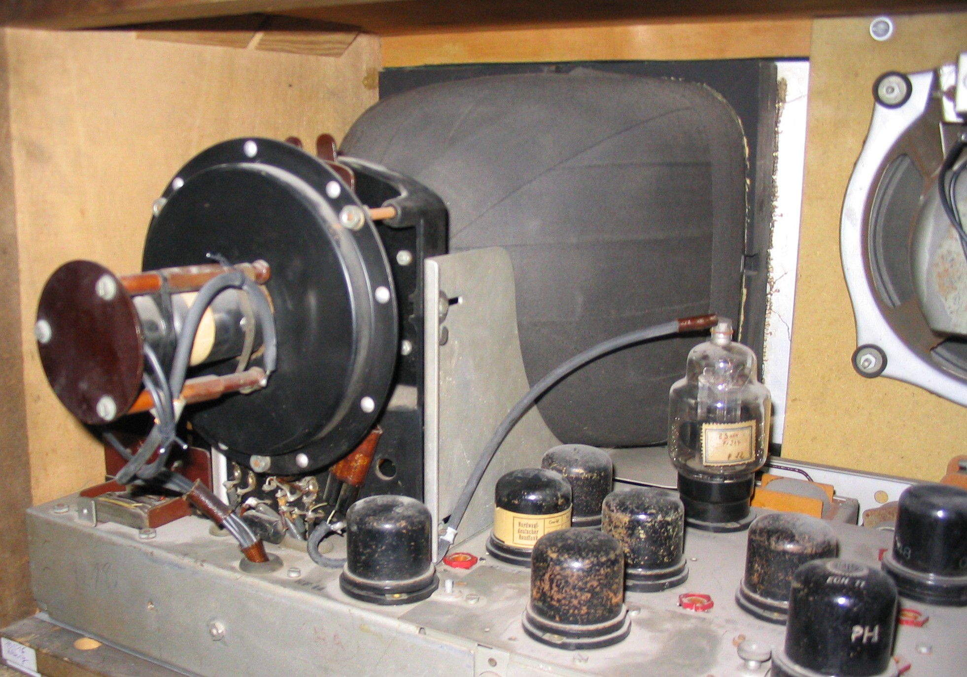
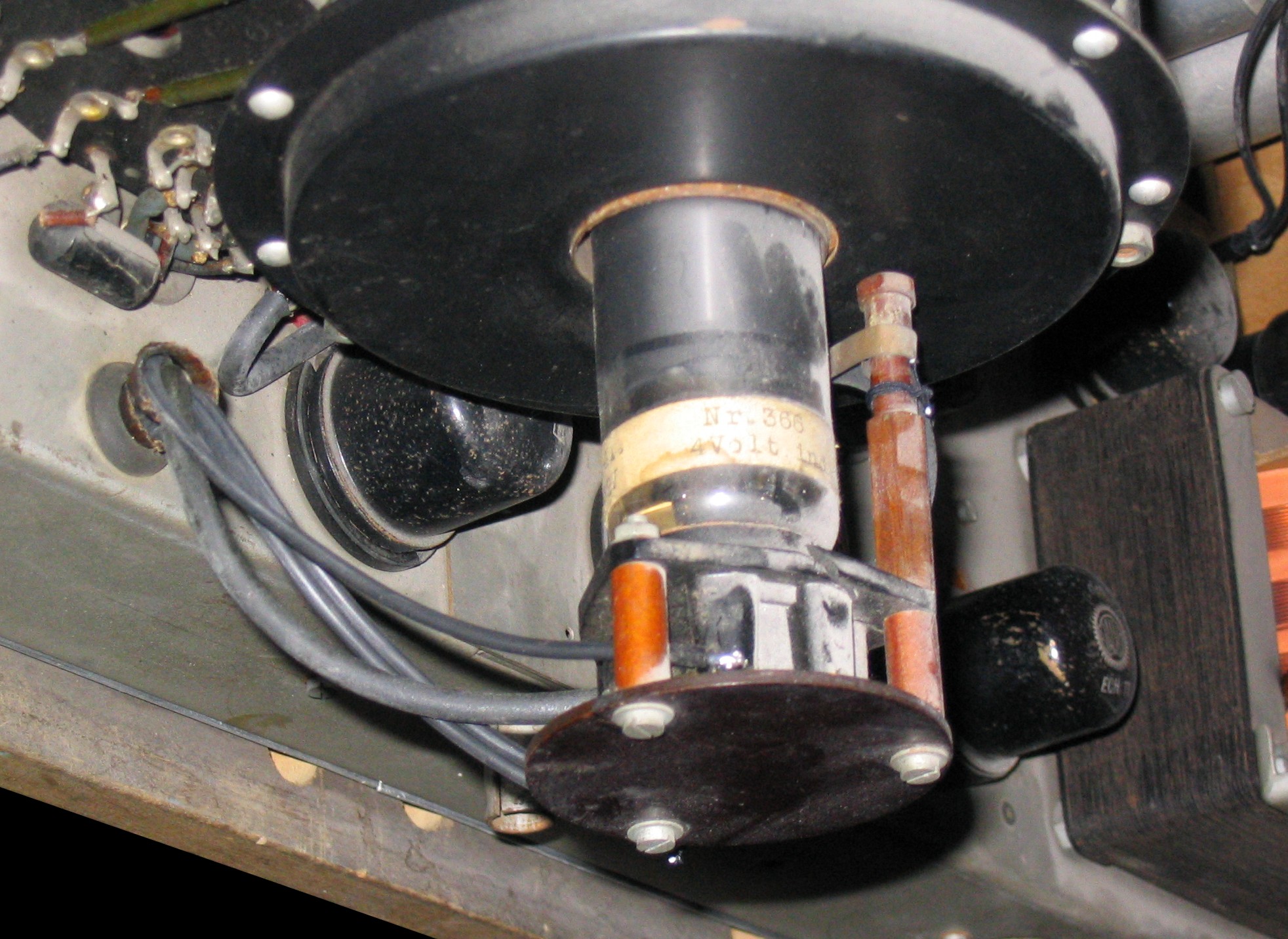
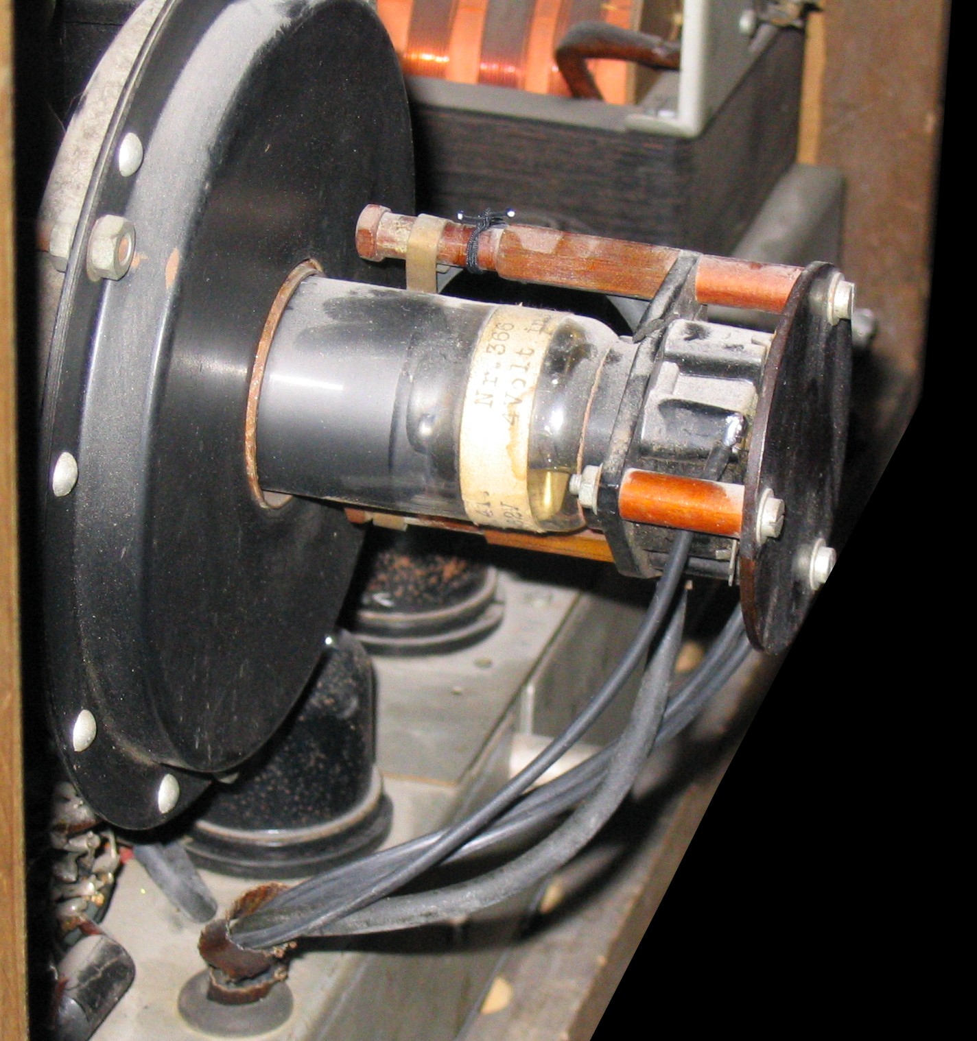
high voltage rectifier with a high voltage transformer. On the left side one can see the
line (horizontal) output tube and high tension rectifier tube. On the right side one can
see the vertical output tube ES 111.
On the left photo one can see the original RFG 5 with a round ceramic plate inside for insulation
reasons. Later RFG 5 did not have this ceramic plate.
|
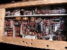
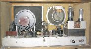
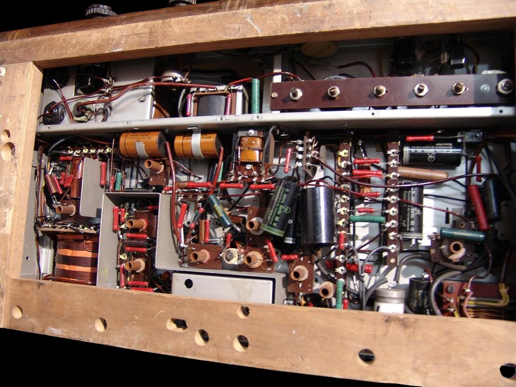
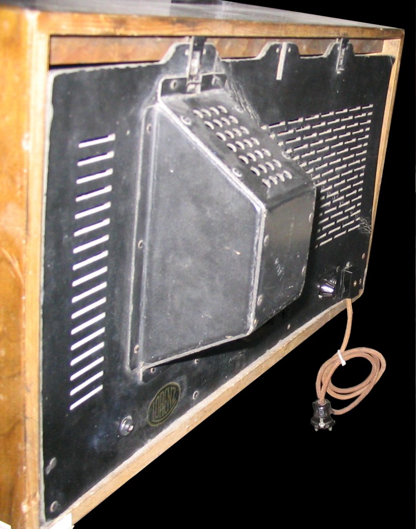
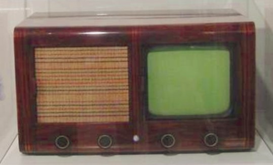
On the left side one can see the set from the below. The chassis looks clean. Some capacitors were recapped, but keeping the old houses of the old caps.
On the right photo one can see the back of this set which is not original. It is taken from a Lorenz E1 receiver.
|

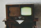
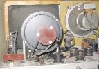
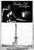
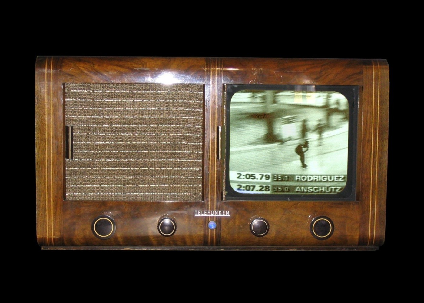
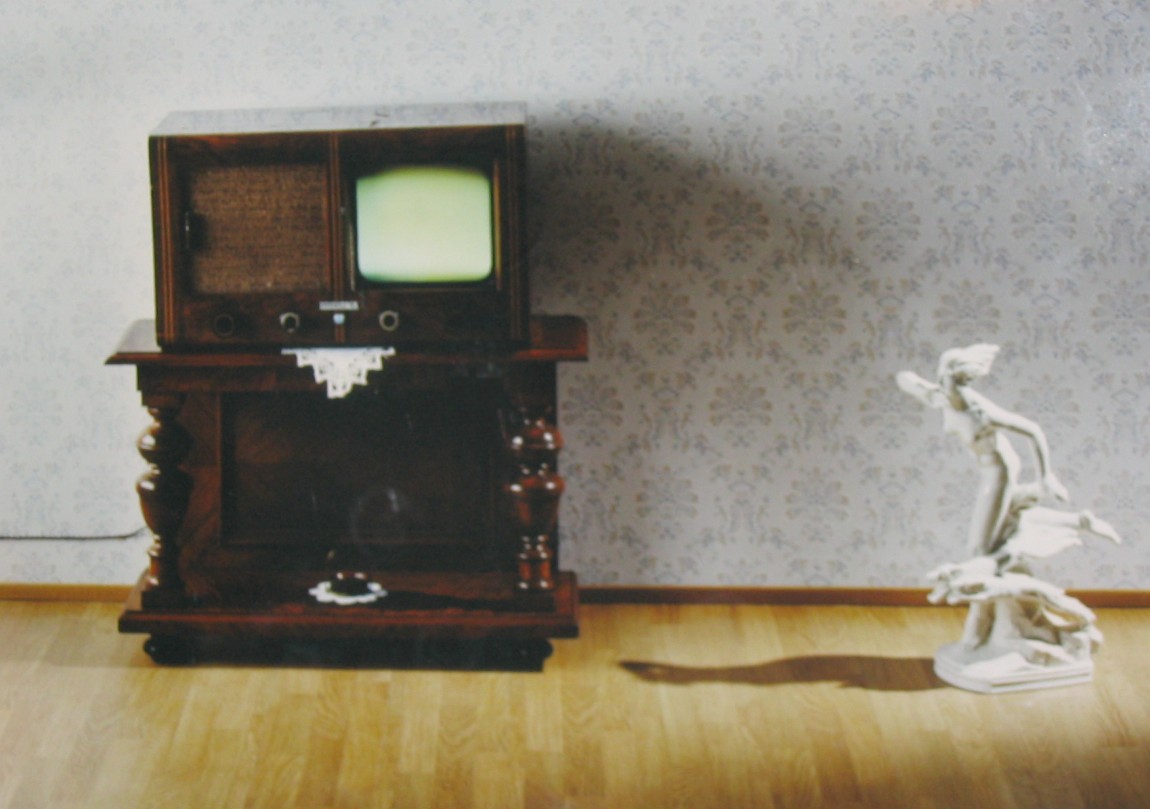
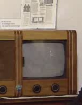
Photo on the left hand: In the same year, 1939, the Film "Who drove IIA 2992?" was produced. The movie shows how television and video phone are used to catch a hit and run driver. It shows a working E1 television set at position 11:17 to 13:40 minutes. The film was found by Claus Peter Gallenmiller. You can start the video by clicking the left photo. The TV set shown here is one of the few surviving complete and functional E1 TV sets that still exists
today. In order to operate the set, an appropriate signal source is required. Since today
we have a 625 line TV standard in Germany, which is not compatible with the old 441 line
standard, today's television programs cannot be shown with this receiver. (The photo above is a fake.) The photo on the
right hand shows the E1 in operating mode with a raster on the screen. It is the photo
of the last time when the E1 was operating. I would like to thank
Mr. August-Peter Nehrig, who made this set accessible to me and gave me the possibility to
document it here, and Steve McVoy of Early Television Foundation for support in providing
this English translation.
|
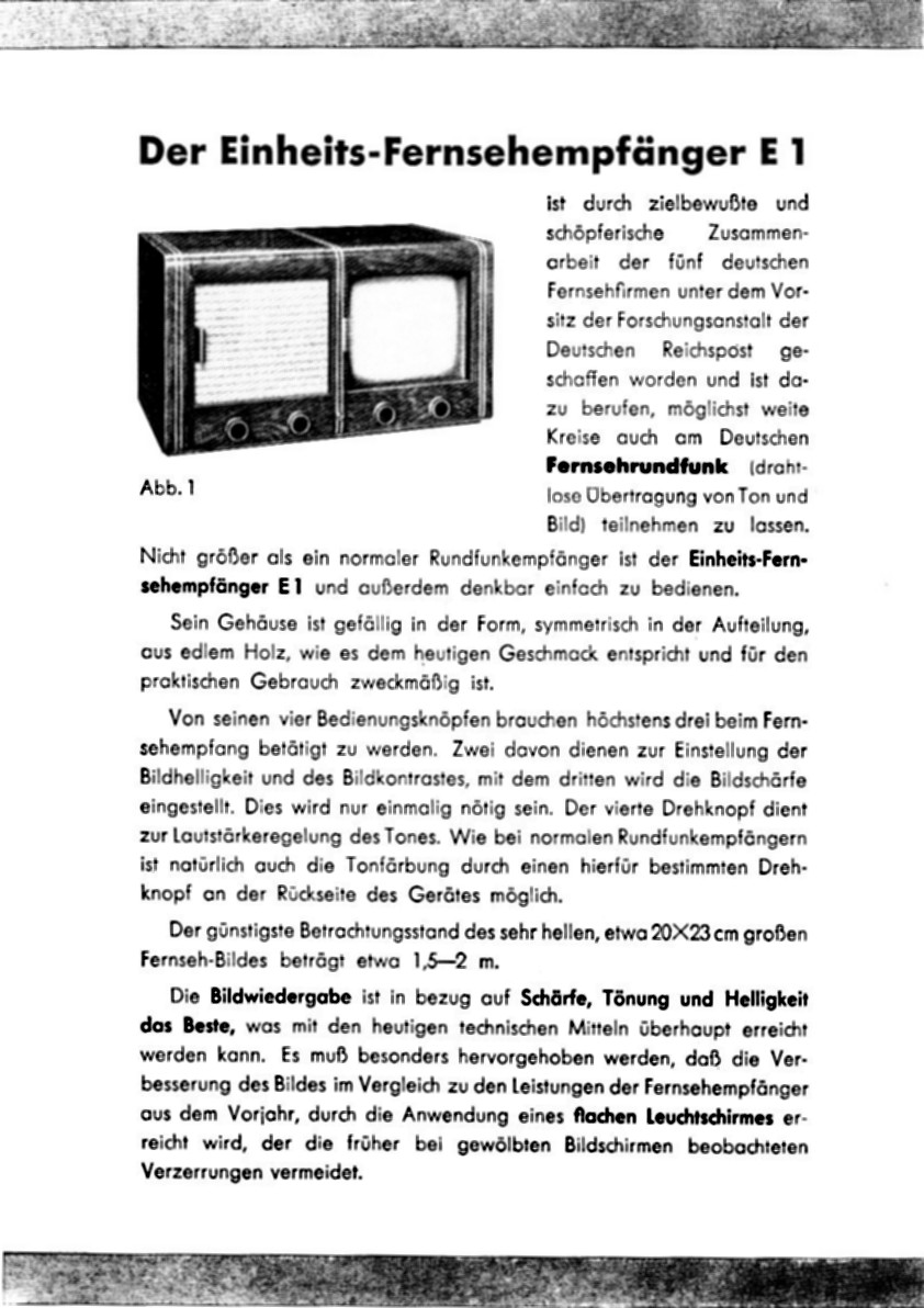
"Der Einheits-Fernsehempfänger E 1 ist
durch zielbewußte und schöpferische Zusammenarbeit
der fünf deutschen Fernsehfirmen unter dem Vorsitz der Forschungsanstalt
der Deutschen Reichspost geschaffen worden und ist dazu berufen,
möglichst weite Kreise auch am Deutschen Fernsehfunk (drahtlose
Übertragung von Ton und Bild) teilnehmen zu lassen. Nicht
größer als ein normaler Rundfunkempfänger ist
der Einheits-Fernsehempfänger E 1 und außerdem denkbar
einfach zu bedienen. Sein Gehäuse ist gefällig in der
Form, symmetrisch in der Aufteilung, aus edlem Holz, wie es dem
heutigen Geschmack entspricht und für den praktischen Gebrauch
zweckmäßig ist. Von seinen vier Bedienungsknöpfen
brauchen höchstens drei beim Fernsehempfang betätigt
zu werden. Zwei davon dienen zur Einstellung der Bildheiligkeit
und des Bildkontrastes mit dem dritten wird die Bildschärfe
eingestellt. Dies wird nur einmalig nötig sein. Der vierte
Drehknopf dient zur Lautstärkeregelung des Tones. Wie bei
normalen Rundfunkempfängern ist natürlich auch die Tonfärbung
durch einen hierfür bestimmten Drehknopf an der Rückseite
des Gerötet möglich. Der günstigste Betrachtungsabstand
des sehr hellen, etwa 20 x 23 cm großen Fernseh-Bildes beträgt
etwa 1,5-2 m. Die Bildwiedergabe ist in bezug auf Schärfe,
Tönung und Helligkeit dos Beste, was mit den heutigen technischen
Mitteln überhaupt erreicht werden kann. Es muß besonders
hervorgehoben werden, daß die Verbesserung des Bildes im
Vergleich zu den Leistungen der Fernsehempfänger aus dem
Vorjahr durch die Anwendung eines flachen Leuchtschirmes erreicht
wird, der die früher bei gewölbten Bildschirmen beobachteten
Verzerrungen vermeidet."
|
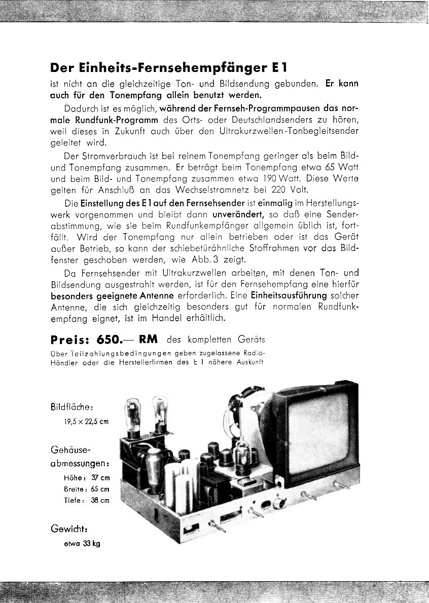
"Der Einheits-Fernsehempfänger E 1 ist
nicht an die gleichzeitige Ton- und Bildsendung gebunden. Er kann
auch für den Tonempfang allein benutzt werden. Dadurch ist
es möglich, während der Fernseh-Programmpausen das normale
Rundfunk-Programm des Orts- oder Deutschlandsenders zu hören,
weil dieses in Zukunft auch über den Ultrakurzwellen-Tonbegleitsender
geleitet wird. Der Stromverbrauch ist bei reinem Tonempfang geringer
als beim Bild-und Tonempfang zusammen. Er beträgt beim Tonempfang
etwa 65 Watt und beim Bild- und Tonempfang zusammen etwa 190 Watt.
Diese Werte gelten für Anschluß an das Wechselstromnetz
bei 220 Volt, Die Einstellung des E 1 auf den Fernsehsender ist
einmalig im Herstellungswerk vorgenommen und bleibt dann unverändert,
so daß eine Senderabstimmung, wie sie beim Rundfunkempfänger
allgemein üblich ist, fortfällt. Wird der Tonempfang
nur allein betrieben oder ist das Gerät außer Betrieb,
so kann der schiebetürähnliche Stoffrahmen vor das
Bildfenster geschoben werden. Da Fernsehsender mit Ultrakurzwellen
arbeiten, mit denen Ton- und Bildsendurg ausgestrahlt werden,
ist für den Fernsehempfang eine hierfür besonders geeignete
Antenne erforderlich. Eine Einheitsausführung solcher Antenne,
die sich gleichzeitig besonders gut für normalen Rundfunkempfang
eignet, ist im Handel erhältlich. Preis: 650.- RM des kompletten
Geräts. Über Teilzahlungsbedingungen geben zugelassene
Radio-Händler oder die Herstellerfirmen des E 1 nähere
Auskunft. Bildfläche: 19,5 x 22,5 cm, Gehäuseabmessungen:
Höhe: 37 cm, Breite: 65 cm, Tiefe: 38 cm, Gewicht: etwa 33
kg."
|

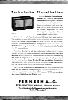
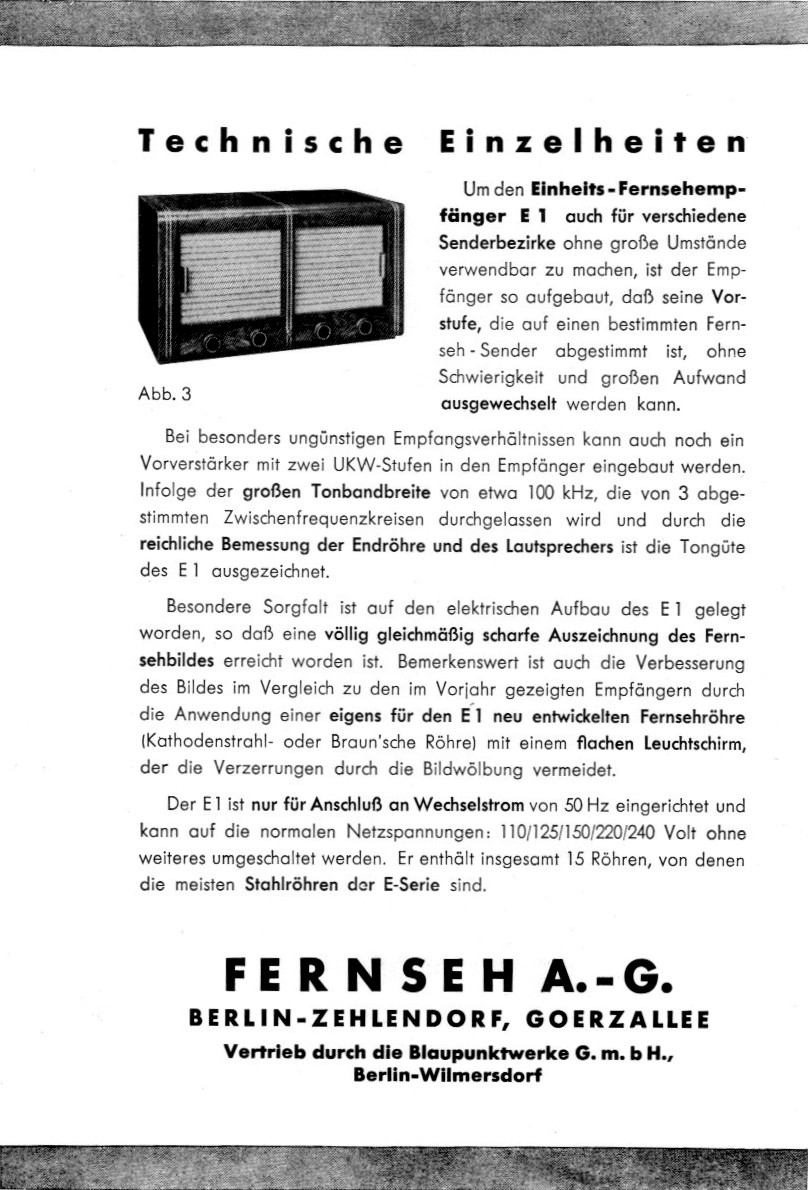
"Technische Einzelheiten: Um den Einheits-Fernsehempfänger
E1 auch für verschiedene Senderbezirke ohne große Umstände
verwendbar zu machen, ist der Empfänger so aufgebaut, daß
seine Vorstufe, die auf einen bestimmten Fernseh-Sender abgestimmt
ist, ohne Schwierigkeit und großen Aufwand ausgewechselt
werden kann. Bei besonders ungünstigen Empfangsverhältnissen
kann auch noch ein Vorverstärker mit zwei UKW-Stufen in den
Empfänger eingebaut werden. Infolge der großen Tonbandbreite
von etwa 100 kHz, die von 3 abgestimmten Zwischenfrequenzkreisen
durchgelassen wird und durch die reichliche Bemessung der Endröhre
und des Lautsprechers ist die Tongüte des E1 ausgezeichnet.
Besondere Sorgfalt ist auf den elektrischen Aufbau des E1 gelegt
worden, so daß eine völlig gleichmäßig scharfe
Auszeichnung des Fernsehbildes erreicht worden ist. Bemerkenswert
ist auch die Verbesserung des Bildes im Vergleich zu den im Vorjahr
gezeigten Empfängern durch die Anwendung einer eigens für
den E1 neu entwickelten Fernsehröhre (Kathodenstrahl- oder
Braun'sche Röhre) mit einem flachen Leuchtschirm, der die
Verzerrungen durch die Bildwölbung vermeidet. Der E 1 ist
nur für Anschluß an Wechselstrom von 50 Hz eingerichtet
und kann auf die normalen Netzspannungen: 110/125/150/220/240
Volt ohne weiteres umgeschaltet werden. Er enthält insgesamt
15 Röhren, von denen die meisten Stahlröhren der E-Serie
sind. FERNSEH A.-G., BERLIN-ZEHLENDORF, GOERZALLEE. Vertrieb durch
die Blaupunktwerke G. m. b. H., Berlin-Wilmersdorf"
|
List of all surviving E1
- The E1 of August-Peter Nehrig, Photo, Telefunken (restored).
- Museum of Communication, Berlin, Photo, Telefunken
- Museum of Communication, Berlin, Photo 1, Blaupunkt
- Museum of Communication, Frankfurt, Photo Telefunken (with replacement speaker grill)
- Archive of the Robert Bosch GmbH, Historical Communication, Stuttgart, Photo, Blaupunkt (with replacement speaker grill)
- Depot of the German Fernmeldezeugamt in Frankfurt-Heusenstamm, unknown brand (complete and in mind condition)
- Museum of Broadcasting Nuremberg-Fürth, Photo, chassis (with main transformer), credits: Michael Roggisch
- The Liesenfeld-collection, Photo, (replica)
- German Radio Museum, Berlin, Photo (replica)
- Museum of Broadcasting Nuremberg-Fürth, Photo, credits: Michael Roggisch, (replica)
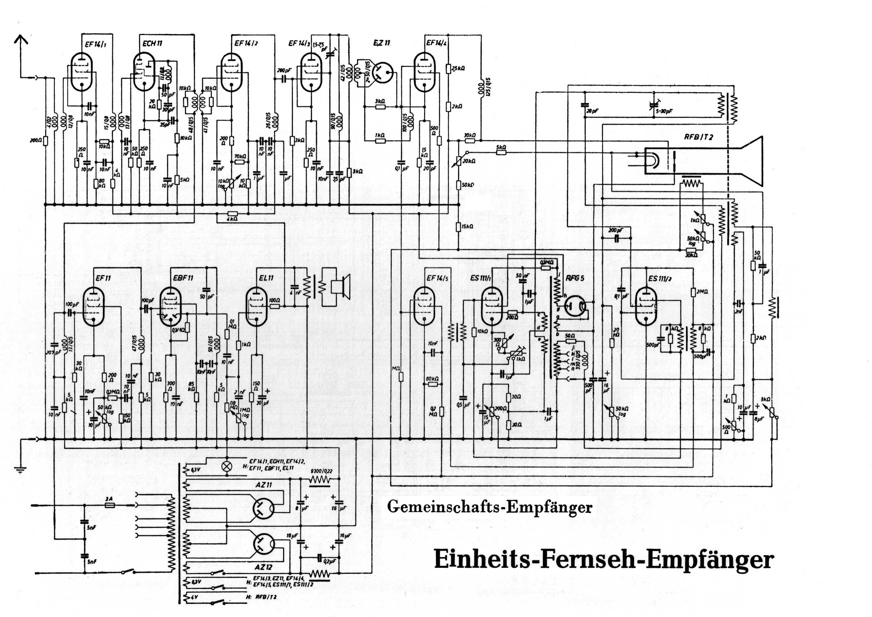
Circuit Diagram
Click here for a JPEG file.
Tubes:
AZ 11, AZ 12, EF 11, ECH 11, EBF 11, EL 11, EZ 11, 5mal EF 14, 2mal ES 111, RFG 5, RFB/T2.
Photos: © Eckhard Etzold, 2004.
 Zur Zur
![[Zurück]](Images/arr-supr.jpg)
Stand: 6. Dezember 2007 |