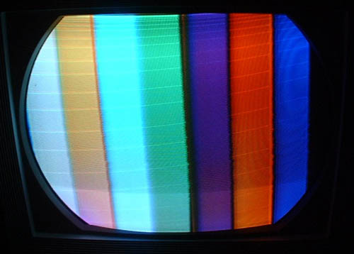
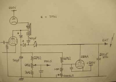
Early Color Television Experimental Pye Color Set Restoration by David BoynesThis set, made by Pye in England, was based on the American NTSC color TV standard of the time. The Pye company had to import the tube and three specialized American tubes, but the set was a purely British design and layout. 7/22/02 The set has developed a fault in the line (horizontal) output stage, I just hope that the flyback transformer has not failed. All picture display components were sourced from America, however, Pye decided to employ readily available European valves (tubes) in the scan circuits. The line (horizontal) output stage has two parallel PL36/25E5 output pentodes and the reclaim diode (damper) is a pair of PY81/17Z3s. For EHT (high voltage), two DY86 diodes are employed in a voltage doubler circuit, these monochrome TV valves (tubes) are not really up to the job, operating very close to their current limits. A 6BK4 serves as the shunt stabiliser (voltage regulator). All the signal circuits are similar to the better specification Pye TV sets of the time, so is the field (vertical) timebase. The NTSC decoder uses a mixture of American and European valves (tubes). All in all this is going to be quite a challenging project. The first stage is to get it operating as a 405 mono set and then finally build some sort of colour pattern generator, or, as stated in your last Email, the possible development of a standards converter employing a high speed computer. The original metal-glass CRT (probably a 21AXP22) had failed, looks as if it has gone down to air. Fortunately Ian acquired an all glass CRT from John Wakely. The replacement CRT is similar to the 21CYP22. The tube is a Mullard branded AX53-10, made in Holland. 7/30/02 I suggested that a simple NTSC color bar generator might be modified for 405 lines, and sent him data on a B & K 1210 I had. By changing the two crystals and readjusting the divide down counters it should work. 8/14/02 I think I can modify the B&K pattern generator. The sync divider circuits are simple multi-vibrators so there should be no problems whatsoever altering those. The time slots for the patterns can remain the same. The principle of operation of the colours is simple, all I have to do is have a sub-carrier oscillator crystal made for the 405 standard. We know that a sub-carrier frequency of 2,657,812.5Hz was the frequency chosen for the 405 colour system, so the crystal will have to be 2,647,687.5Hz. 8/15/02 I suggested that a MC1377 Video Encoder chip, used in consumer camcorders, might work to convert RGB input to 405 line NTSC video The MC1377 is readily available at very low cost. Reading through the specification I'm certain that it will perform OK as a 405 NTSC encoder. Actually a 625PAL to 405NTSC converter can be easily realised if a standard PAL decoder is employed, the RGB outputs could supplied to three FIFO line store units, the converted RGB signals then are fed to the MC1377. The converter would be a simple line dropping type, but it would still be colour. I've still got the artwork for the FIFO line store board. Although the original ADC chip is likely to be no longer available. It was a type ADC302. I could even consider the old CA3306 as a replacement to get the project started. The EHT (high voltage) problem appears to a leaky 25Kv capacitor. I think I could leave it out as the replacement CRT has a graphite coating. 9/4/02 I sent David the B & K pattern generator and manual. After studying the circuit of the B & K colour pattern generator I'm certain that it can be easily converted for 405 NTSC operation. To produce the sync pulses only three of the four existing divider stages will required, two to be modified to divide by nine and the other to divide by five.The remaining divider might used to supply the horizontal lines generator. I'll have to find a firm to make the special crystals. The sync crystal works out to be 121.5Khz and the colour crystal is to be 2,647,687.5Hz. I'm assuming that for 405 colour the principle of operation will be the same as for 525 lnes, that is the subcarrier frequency minus the line frequency. 2,65,812.5 - 10125. 9/12/02 I've ordered the special crystals for the B & K colour generator. There is no problem with the subcarrier crystal, however, the 121.5Khz crystal could not be made, the crystal firm have offered to make a 1.944Mhz item instead. I'll have to divide that frequency by 16 to obtain the required 121.5Khz. I've hooked up a sync pulse master oscillator which consists of a 555 timer chip to the B&K colour pattern generator. I've decided to to retain all the five divider circuits. The first in the chain divides the 121.5Khz oscillator output down to the 405 twice line frequency of 20250Hz. The other dividers are set to divide by 9, 3, 3 and 5 in that order. I found a 2,457,600Hz crystal and have fitted as a substitute for the original 3.56Mhz crystal into the generator, the results can be seen in the attachment. It proves that the colour circuits in the Pye 405 set are operational. I've received confirmation from the crystal company that the special crystals for the B & K generator should take about four weeks to deliver to my address. I've improved the colour signal for the Pye CTV. I've added an emitter follower buffer stage from the baseband output of the pattern generator and fed the video to a spare system modulator. I've also added a sync tip clipper to set the pulses to the correct height, the field sync pulse was of a greater amplitude compared with the line pulses and this did not suit the system A modulator. I'll leave the project for the time being and wait for the delivery of the special crystals.
10/1/2002. I fitted the correct colour sub-carrier crystal into the B & K pattern generator yesterday, the attached picture shows the colours are in the correct positions on the screen of the receiver. That is, according to specification of the B & K colour generator. The next step is to make up a circuit for the 1.944Mhz sync pulse crystal 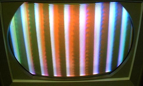
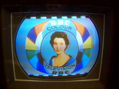
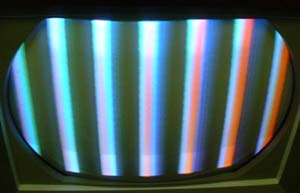
11/14/02 As the attachment shows I'm having some real success with the 405 line colour set, colour bars at last! The TTL derived sub-carrier was not a success so for the time being the sub-carrier source is a signal generator, it is likely that the TTL signal was too rich in harmonic content and is not a pure sine wave. I'm not going to give up on the digital sub-carrier, I'll pass it though a tuned circuit to remove all the harmonics and leave only the fundamental. The sub-carrier regenerator in the set consists of a collpits oscillator and reactance valve to control the frequency and phase. At first sight the circuit looked quite a fearsome thing, however, after spending some time tracing out the circuit it became that the arrangement is quite simple. The valve used in this stage of the receiver is an ECC81/12AT7. It will be noted that this receiver does not employ a crystal to control the frequency. A simple twin diode discriminator supplies the reactance valve with the control voltage, the burst amplifier and gate is a PCF80/9A8. There still a lot of work to do on this set and the colour signal source. 5/11/12 Here's a picture taken from the screen of the 405 line Pye CTV.
Still got frame linearity problems with this set. Just about all avenues have been explored, only the scan coils left. The frame timebase circuit is similar to that used in the Pye VT17, an ECC82 as the oscillator and a PL82 is the output. The tuner, IF stages sound and vision are also VT17. The luma amplifier is a PL83 and the colour difference amplifiers are PCF80s. The line oscillator resembles that used in the V14C. Two parallel PL36 valves employed in the line output stage. The booster diodes are two PY81s. Three DY86s are used in the EHT circuit.
Components supplied from the United States are the original CRT, which is an RCA 21AXP22, the scanning yoke assembly, the special 6BY6 valves used in the colour demodulators and the CRT mask. There's a lot of RCA 21-CT-55 influence in this set. Must not to forget the shunt stabiliser tube, the 6BD4A. Danger X-rays! It is believed that this receiver is the only working 405 line colour set, well it works in a fashion. There's plenty work to be done on this receiver. |