
Early Electronic Television
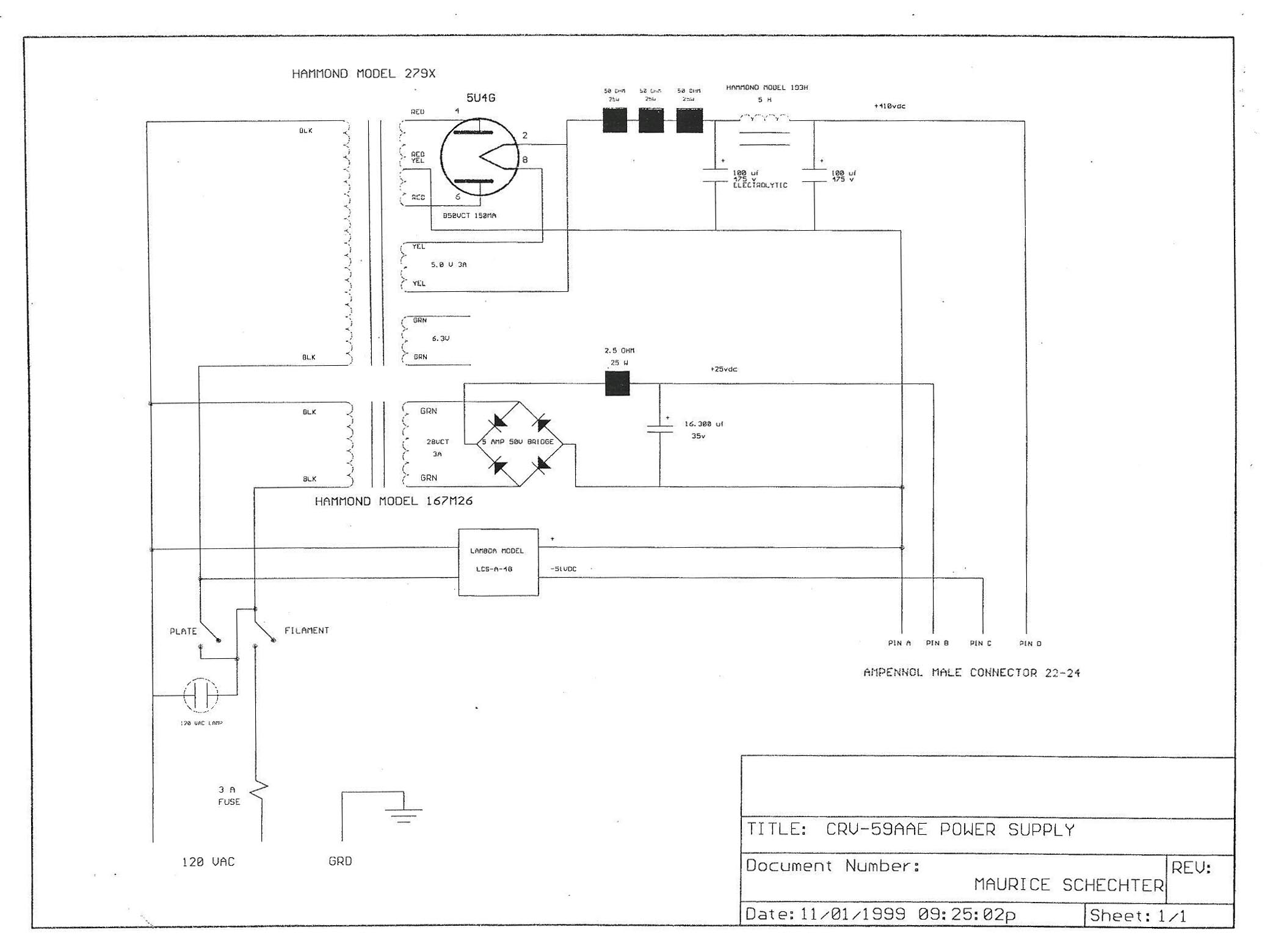
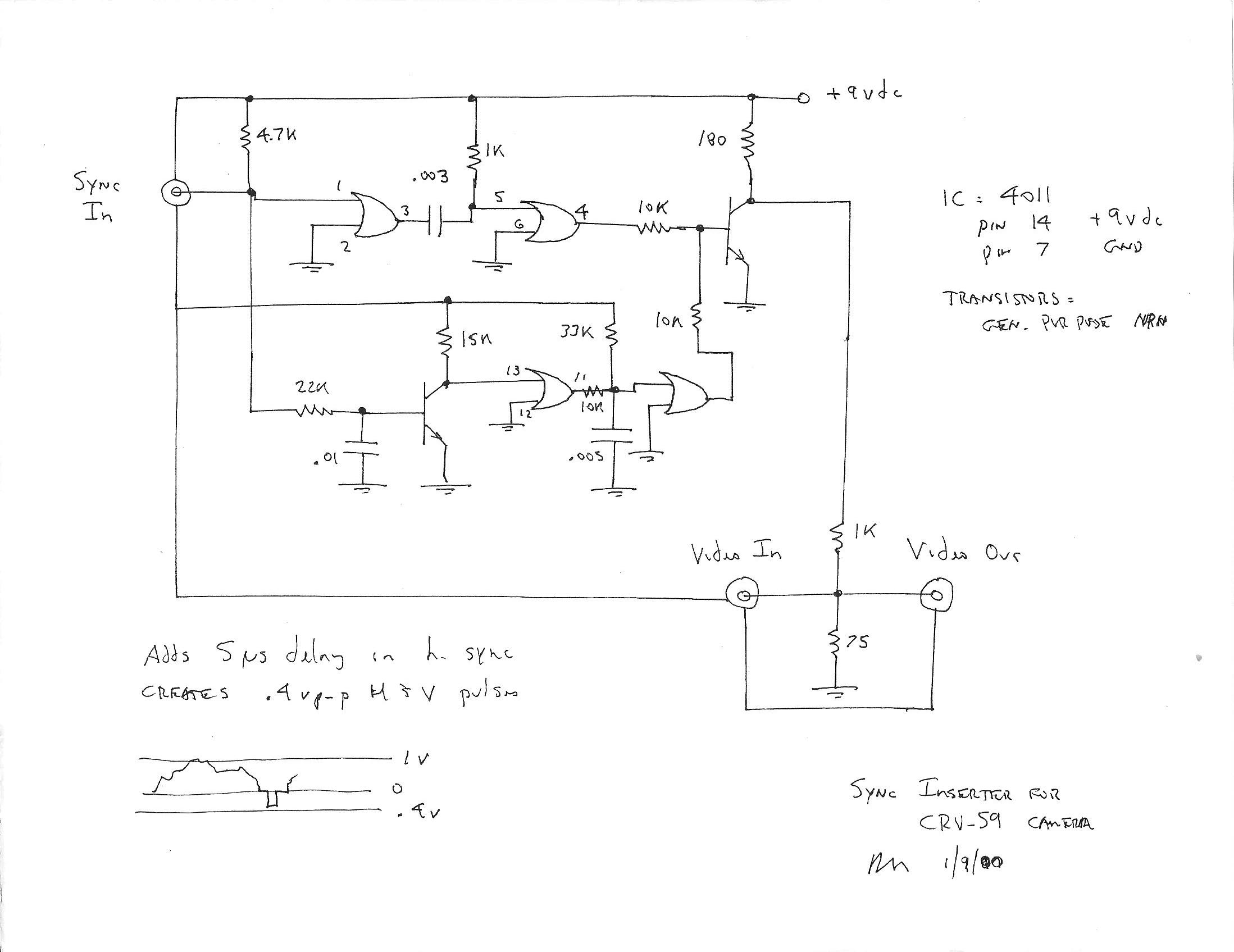
CRV-59 Military CameraWe have modified our camera for 525 line/60 fps operation. Here is some information that will be helpful to those who attempt this. Power Supply. The camera needs +400vdc @about 200 ma, +24vdc @ about 4 amps, and –50vdc at about 10 ma. The schematic from Maurice Schechter uses a 5U4 tube. I built mine using a power transformer from an old TV set, with silicon diodes rather than the 5U4. For the 24vdc, I used a Radio Shack filament transformer with a low voltage silicon bridge. For the –50v, I used two small 24v Radio Shack filament transformers and a low voltage bridge. Camera Modification. The CQ article by Donald Stoner describes how to modify the camera. Ignore the part about changing the filament supply – it is easier just to use 24vdc to power the camera. Do the modification to the horizontal and vertical oscillators. Camera Restoration. The 4 section electrolytics are almost always bad. Replace them before you start. The capacitors are military grade, and don’t need to be replaced, except for one paper capacitor (on the back panel) which will usually be bad. The iconoscope filament is driven by a 15,750 AC source. Be sure to measure the voltage on the pins of the tube socket and set the filament voltage pot for 6 v before you plug in the iconoscope. Most of the 1846s around are bad, usually gassy. You will be lucky if yours is good. They require a huge amount of light even when good. Adjusting the shading controls must be done each time you change the lighting. At best, the picture from the camera is pretty bad. Combining Sync and Video. The circuit I included does a pretty good job. All the parts are available at Radio Shack.
|