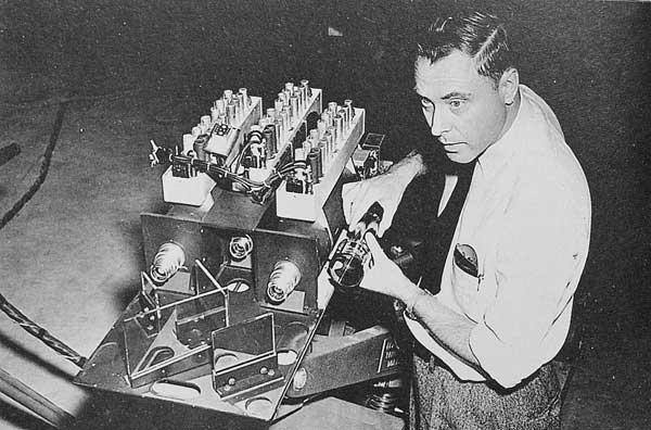
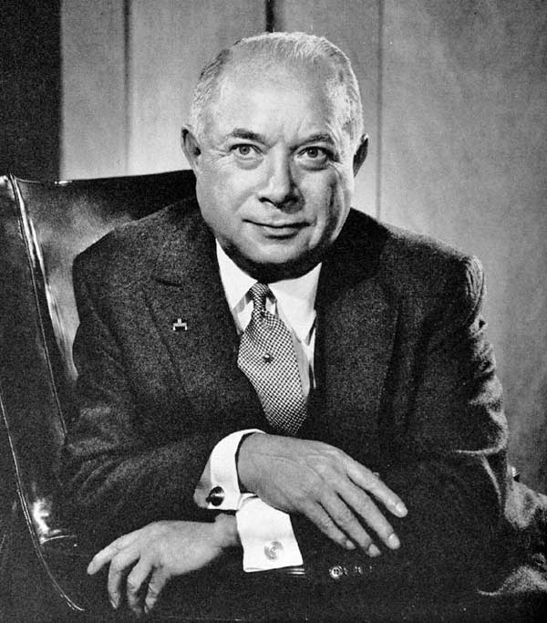
Early Television RCA TV Development: 1929 – 1949By Richard Brewster AWA Review, Vol. 26, 2013 Whilethere were others working on electronic TV, RCA’s David Sarnoff determined to produce a working system with the help of his former countryman, Vladimir Kosma Zworykin. Sarnoff had taken an interest in Zworykin’s work at Westinghouse in 1929, and had begun funding his work there. (1) Westinghouse had little interest in the enterprise. GENERAL ELECTRIC Meanwhile, just a few hundred miles away in Schenectady on September 11th of the previous year, General Electric engineers, directed by E. F Alexanderson, managed to broadcast the world’s first television play, The Queen’s Messenger to a handful of viewers. The Washington Post reported, on September 21st, that it was received as far away as Los Angeles. The mechanical scanning system employed three projectors, each equipped with a 1000-watt lamp directed against a rotating spiral-holed disc. A lens trained the resultant pattern of 24 lines of light on the actors. Reflected spots of light were picked up by a pair of photocell-amplifier units and converted to an electrical video signal.
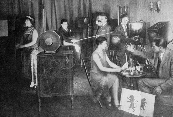
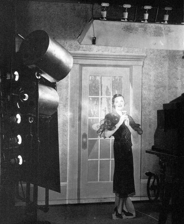
The room was dark except for the light from the scanning unit
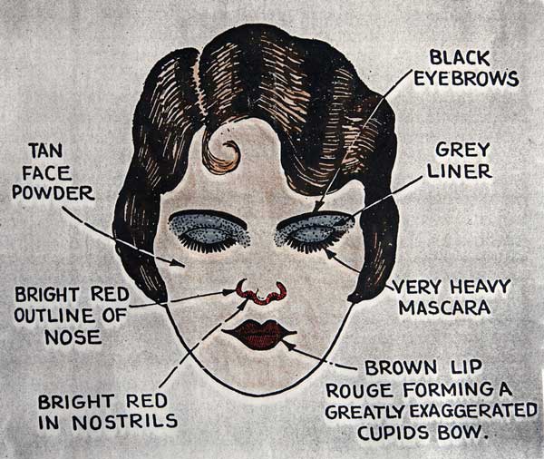
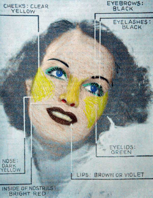
Special makeup was developed to best reproduce the faces of the actors
WESTINGHOUSE Meanwhile, back at Westinghouse, KDKA, under the direction of radio pioneer, Frank Conrad, was also broadcasting pictures with a similar mechanical camera. But Zworykin, eager to develop an all-electronic television system, had been working to improve his iconoscope since the early 20’s. Now, Sarnoff, in an arrangement with Westinghouse, began funding Zworykin’s development of the iconoscope as well as his receiving tube – the kinescope. The 7” by 20” tube, fabricated by Corning Glass was given a willemite phosphor screen prepared by Zworykin’s group. External vertical deflection plates as well as horizontal deflection coils were employed for scanning. Second anode voltage was 3000. The set was first demonstrated in the lab in May of 1929, and radio transmission, using separate channels for video and sync, was effected in August of that year. Seven of these sets were built. (3)
RCA TAKES OVER In early 1929, Zworykin famously told Sarnoff that he hoped that in two years and at cost of $100,000, he could produce a workable TV system. Sarnoff replied, “All right, it’s worth it.” (4) Finally, in 1930, Zworykin’s group moved to the RCA labs in Camden, NJ together with some of the GE engineers who were responsible for the 1928 Queen’s Messenger broadcast. (5) Now, work could begin in earnest.
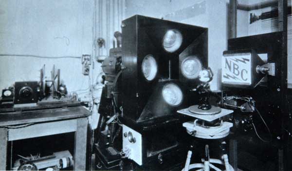
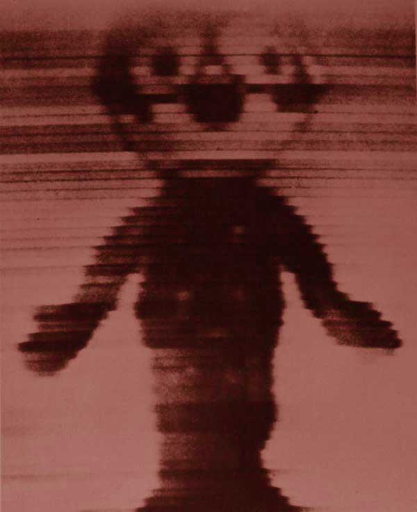
Meanwhile, RCA engineers had constructed by the summer of 1929, a 60-line, 20-frame-per-second mechanical scanning camera, and were transmitting pictures including images of Felix-the-Cat using RCA’s FCC authorized call, W2XBS. (6)
During 1930, the Camden group built several 60-line mechanical receivers to further evaluate the mechanical system
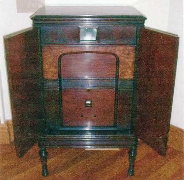
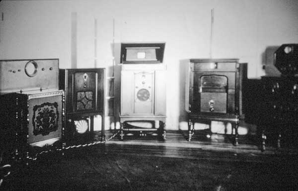
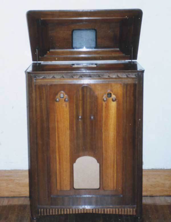
Felix was seen as a red and black image with the disc curvature being quite apparent. Retired RCA engineer, John Paul Smith explained that, “We gave a demonstration for General Sarnoff of the status of television receivers at that time.”(7) A demonstration was arranged with Zworykin’s Westinghouse ‘lab’ set, a mirror-in-the-lid set, the RCA 60-line mechanical set, and the GE ‘Queen’s Messenger image monitor.
Three sets of a 60-line mechanical camera system, this time employing eight photocells in order to provide greater sensitivity, were subsequently built in the RCA Camden development lab on the 6th floor of building two. The associated electronics racks were constructed by J. M. Morgan and J.P. Smith. According to Smith, the scanning and PJ-19 photocell pickup assemblies were built by M. Trainer and J. Briggs.
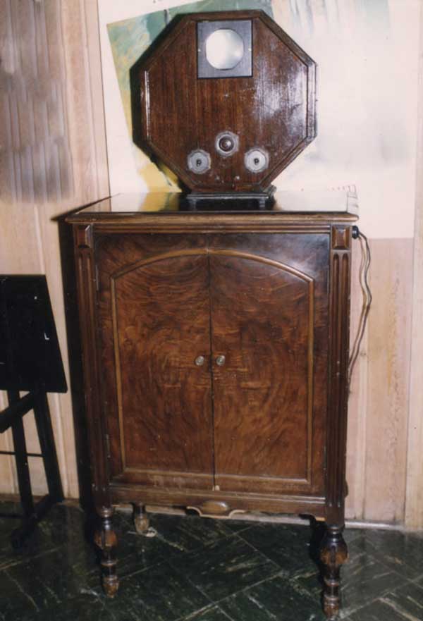
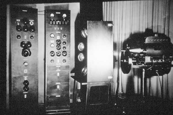
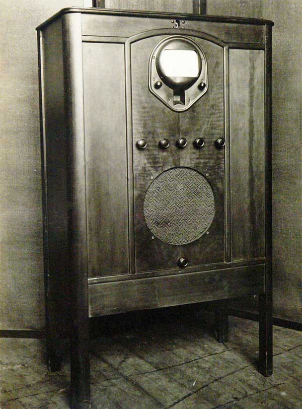
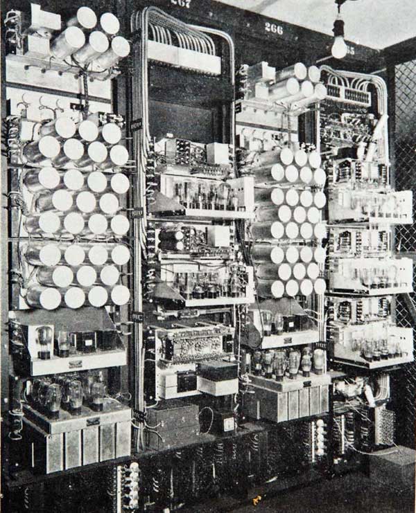
One of these sets was provided (sold?) to CBS for their experimental broadcasts. (7) CBS’s use of this unit was the subject of my AWA Journal article, The Original Television Girl, Oct. 2004. (8) RCA 1932 TEST SET In May of 1932, RCA demonstrated their latest TV system using the newly developed 120-line, 24-frame kinescope (Zworykin’s name for the CRT) receiver. Picture and sound were tuned separately and the CRT had a green phosphor. (9) In 1984, RCA engineer, Jeff Lendaro discovered an example of this television in an RCA warehouse in Indianapolis. It was being junked and he rescued it! The video receiver is an 11-tube superhet tuning from 35 to 55 MHz. The audio receiver is a 10-tube super, tuning between 55 and 75 MHz. The power unit supplied 1000 and 6000 volts.
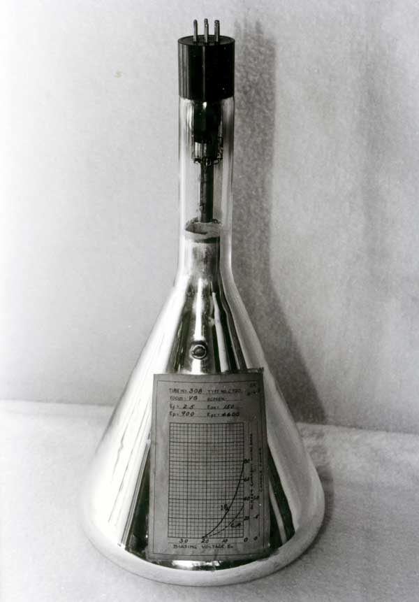
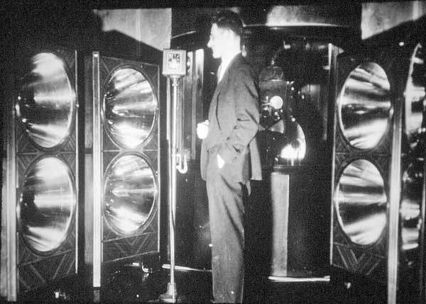
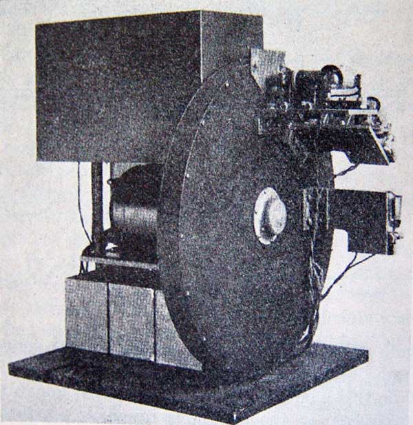
The experimental kinescope still has its attached data sheet. (10) The 120-line images transmitted to the 1932 test set were produced by giant photocell reflector assemblies, required to pick up as much light as possible from the subject illuminated by the scanning beam. The intense light was generated by a 150 amp arc projector and ‘chopped’ by the 120-hole scanning disc. The resultant image was still very noisy according to RCA engineer, Smith, who was also involved the design of this system. It was RCA’s final mechanical TV effort. (7)
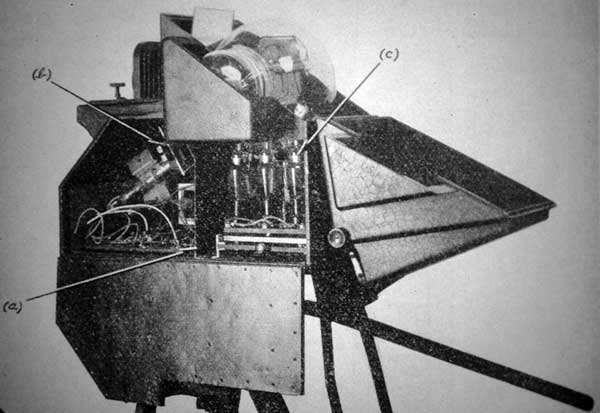
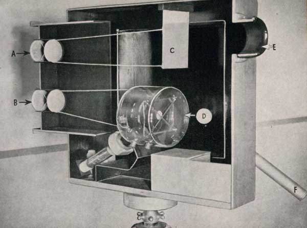
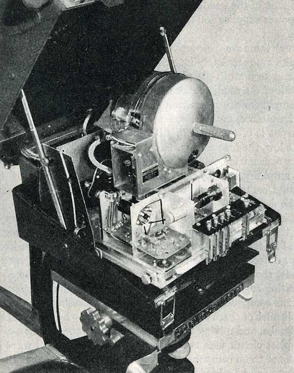
RCA engineer G.L. Beers believed, concerning TV viewing at that time, “In the case of usual sound broadcast program, the listener can obtain some measure of enjoyment while reading or engaged in some other diversion. To any degree of pleasure from a television program requires the entire attention of the observer.” (11) Television, RCA, volume 1, pg. 201. ELECTRONIC CAMERA DEMONSTRATED In February of 1933, a TV demonstration finally incorporated an electronic camera, equipped with Zworykin’s recently developed spherical iconoscope. (12) An inside view of this camera reveals a top-mounted mirror which reflected the image on the mosaic to the operator. Three tubes provided two stages of video gain as well as blanking amplification.
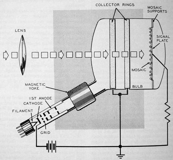
Smith explained that for signal transmission, they developed a crude coaxial cable consisting of a 4 mil copper-plated steel wire threaded through rubber tubing. (7) A simplified explanation of iconoscope operation is as follows: An image focused on the photosensitive mosaic globules liberates electrons leaving them positively charged in ‘bright’ areas. The electron gun produces a scanning beam that additionally charges the globules. This differential charge is capacitively coupled to the signal plate, generating a video signal. (13)
Prior to the electronic camera, the mechanical scanning system generated its own sync pulses by providing a signal that enabled the receiver disc motor speed to lock to that of the transmitting disc. But the electronic camera required sync pulses to direct the scanning beam as well as to provide sync for transmission to the receiver. An opto-mechanical device, consisting of a rotating disc having 243 apertures (for horizontal) and 2 apertures (for vertical) along with photocell assemblies, did just that.
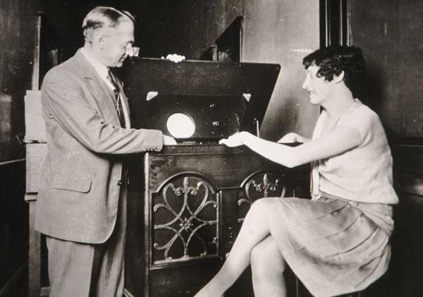
For the February1933 television demonstration, a newly-developed test receiver reproduced a 243-line, interlaced, 60-frame picture, although officially, RCA claimed only 240 non-interlaced lines. Interlacing involves transmitting odd lines of a picture and then the even lines, while eliminating noticeable flicker and requiring less bandwidth than transmitting all the lines at once. The RF circuit incorporated one local oscillator feeding two mixers and their respective IF strips. The sound channel had 3 IF stages with AGC, while the video had 5 IF stages, also with its own AGC. The sync and deflection circuits had 9 tubes driving a vertical deflection yoke and horizontal deflection plates. Second anode voltage was 4600. The exotic power transformer had 6 filament as well as high and low voltage windings. Tube complement, including 4 rectifiers, was 33 plus the 9-inch, vertically mounted green-screen kinescope.
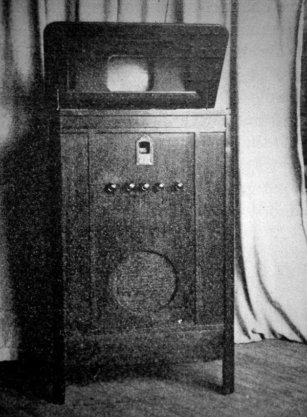
An explanation of the CRT vertical mounting is in order here. Zworykin first used this arrangement in 1929 and RCA engineers continued it into the 1940’s. Firstly, the early tubes were long, partially because the electron gun was rather complex, incorporating deflection plates for electrostatic horizontal deflection. Vertical deflection was magnetic, necessitating a deflection coil that further lengthened the neck of the tube. But the real problem was the limited deflection angle that could be accommodated. Wide deflection angles would require greater horizontal and vertical drive. In addition, style was important. A television receiver had to look much like the console radio of the day and a lift top mirror displaying a reflected image was thought to be the solution. Also, room light reflection on the CRT was considered to be problematic while it was believed that the mirror provided a wider audience view. (14)] In a makeshift studio, the 1933 demonstration included the televising of Mrs. Ruth Trainer, who sang a selection accompanied at the piano by Mrs. Katherine Bedford. The very insensitive iconoscope pickup tube required intense lighting. In this scene, 17 kilowatts of light were used! Close examination of the photo reveals that a heat-tolerant stand-in kindly replaced Mrs. Trainer during some of the testing!
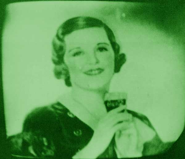
The received image had a green tint INEXPENSIVE TV During the summer of 1934, a five-inch direct-view TV was developed by the Research Division of RCA to demonstrate that a relatively inexpensive consumer television receiver could be produced. (15) It displayed a five-inch direct-viewed picture with a line resolution which, by then had been raised to 343. Newly available type 53 dual-triodes, as well as fewer IF stages, reduced tube count to 19. The use of a five-inch CRT allowed a less expensive, relatively low 2300-volt second anode power supply. AGC and a newly-developed automatic background control were part of the circuitry. Horizontal deflection plates were eliminated, reducing CRT complexity and cost. Sub-assemblies for various functions were employed which could be built and tested individually. The lab report did not mention estimated selling price but did indicate that the receiver had operated for over 700 hours of actual use. This set was apparently never publicly demonstrated and the report on its development was stamped Confidential.
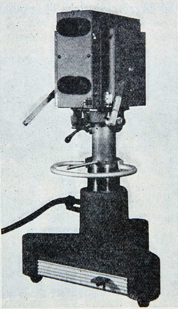
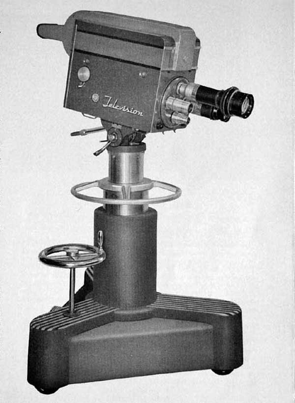
1936 TV DEMONSTRATION In May of 1935, RCA president Sarnoff announced to stockholders, that a million dollars (Big money during the depression!) would be allocated for the development of a TV system which would include the construction of studio facilities as well as a new transmitter and antenna atop the Empire State Building. In mid-1936 testing began in New York City’s Radio City studio 3H. (16) The new twin-lens camera provided a lens for the iconoscope and allowed the operator to view, through a second lens, a bright, inverted image on a ground glass. The previous camera gave the operator a dim image reflected from the iconoscope mosaic.
An open view of the camera shows the new cylindrical Ike It still required intense lighting (1000 to 2000 foot-candles) and was the industry standard camera well into the ‘40s, when the highly-sensitive image orthicon became available.
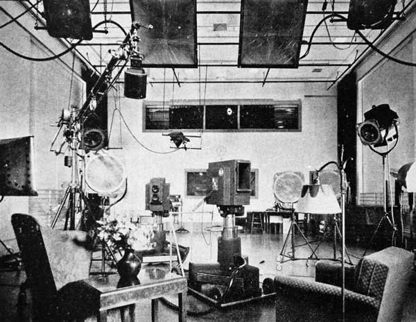
The Radio City studiowas big: 50 by 30 feet and 18 feet high. Three cameras were available for use, with 6.5, 14, and 18-inch lenses. Up to fifty kilowatts of lighting could be used, supplied by DC generators. (17)
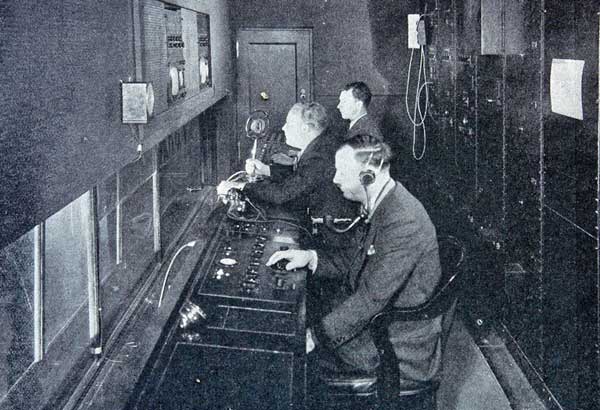
In addition, RCA engineers designed and equipped the control roomoverlooking the 3H studio Duplicate, redundant sync generators (which had, by now, replaced the mechanical unit) were continually energized to insure stability. They consisted of a 20,580 cps oscillator, locked to the 60-cycle line driving ‘stair-step’ counter frequency dividers incorporating the recently- developed type 79 dual-triode. (18)
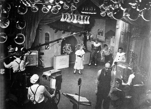
TV during the 1936-1937 experimental work still required unusual makeup as can be seen The RR-359 receiver, originally with a nine-inch screen, was designed for use in the 1936 343-line tests. This 32-tube set, plus CRT, used older 6D6’s, some octal types, as well as experimental tubes. Separate video and audio IF amplifier strips were employed. The picture was still green and black. (19)
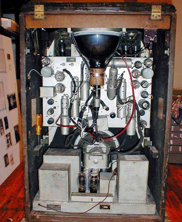
A rear view of the RR-359 shows the unusual IF amplifier tube mounting method designed to reduce the lead length between stages. Similar to earlier designs, this set had a power supply with two low voltage and two high voltage rectifiers. The sound channel had a pair of 2A3’s for audio output as well as bass and treble controls. Also featured were coarse and fine vertical and horizontal hold controls suggesting the future move to 441 lines.
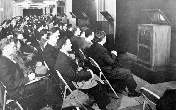
The RR-359 promotional photo reads,“This picture shows you how the National Broadcasting Company’s experimental television is being received in the homes of a small group of engineers. The receiver set – which is in a state as experimental as television programs – is about the size of a console radio.” On November 12, 1936 broadcast station executives from around the country were invited to see a demonstration of RCA’s newest TV system. Almost 300 viewed programming on RR-359 sets on the 60th floor of the RCA building. Transmissions were relayed from the one-mile distant Empire State Building. Luncheon was served in the Café François, Rockefeller Center. (20)
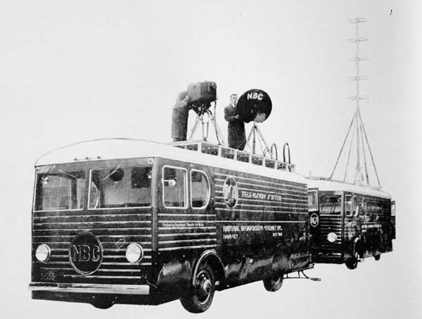
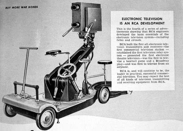
MOBILE TV VAN SYSTEM On December 12, 1937, a mobile system, consisting two 26 foot busses was delivered to NBC in New York City. One motor van provided two portable single-lens iconoscope cameras and their support equipment. The second van contained the177 MHz transmitter with antenna which could relay a remote pickup to the Empire State Building (21)
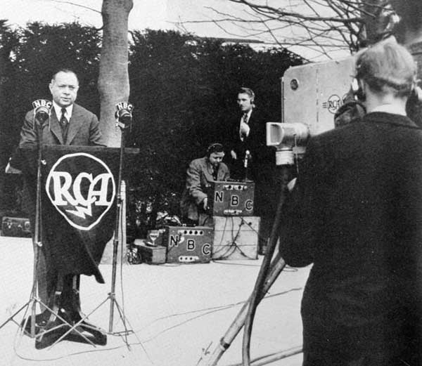
Then on September 15, 1938, NBC conducted the first sidewalk interview with passers-by in Rockefeller Plaza. (22) TV PRESENTED TO THE PUBLIC David Sarnoff unveiled RCA’s 441-line television system to the public at the New York World’s Fair in April of 1939, having spent 10 million dollars. Never the less, it was still experimental, having not been given the go-ahead by the FCC. (23)
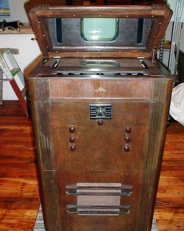
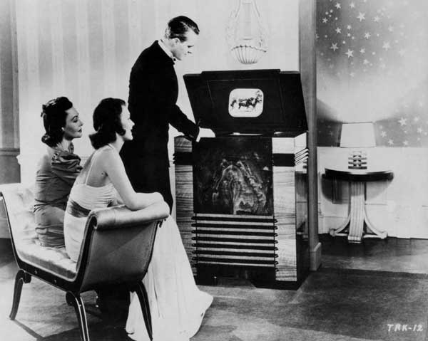
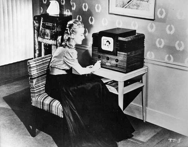
The top-of-the-line TRK-12, a 12-inch, $600 combination TV and radio was first offered to the public at the Fair. The 1939 RCA publicity photo depicts the mirror-in-the-lid twelve-inch, $600 combination TV and radio in an upscale home setting. It tuned channels 1 - 5, 44 to 90 MHz. Finally the picture was black and white.
Tube complement: 23 including 12AP4. In addition, the audio amplifier, for AM sound, was included as part of a separate multi-band radio receiver. RCA also offered the TRK-9 and TRK-5, nine-inch and five-inch direct-view TV receivers. The table-model TT-5 was offered for only $200, but it required a separate radio connection to provide the sound amplifier and speaker. Thus, the set was often pictured with a console radio nearby.
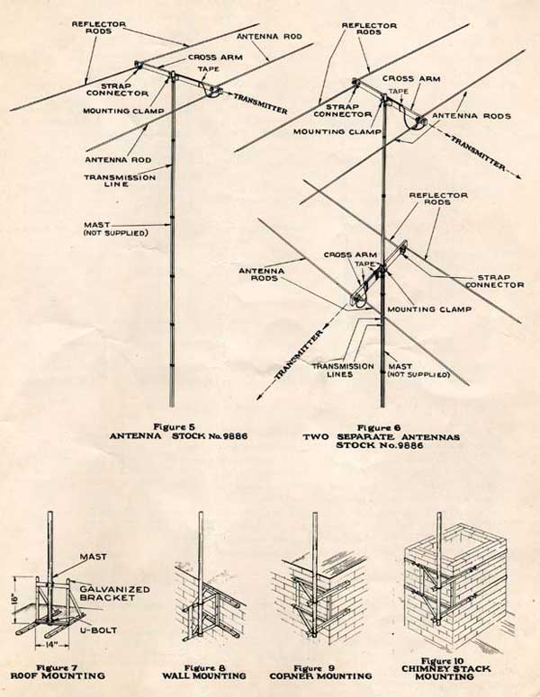
In fact, late 30’s RCA radios often were advertised as ready for use as an adjunct to a future TV. This would hopefully encourage folks to purchase an RCA radio rather than to wait for TV. RCA designed everything needed for its new system of television, even receiving antennas. Interestingly, a second antenna is recommended in order to receive an additional channel from another direction.
BROADCASTING During the year from first the initial World’s Fair telecast, NBC broadcast, with virtually no sponsorship, 601 hours of programming, including over 60 dramatic productions and numerous sporting events. In March of 1940, scenes from an opera were telecast from the NBC studio.
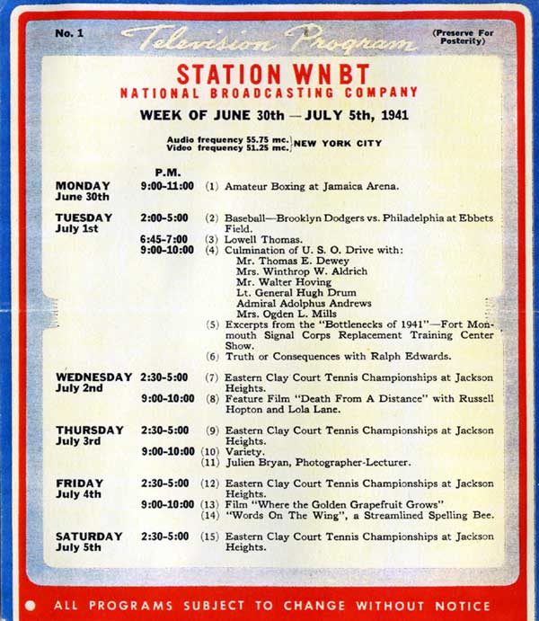
Test patterns were on the air for an additional 800 hours. It was estimated that there were about 3000 TV sets in use in the NY City area in April of 1940. (24) During this period, required TV makeup consisted of; Lips: indian red-brown, Complexion: ranging from burnt-orange to peach-tan, eyes: outlined in brown. (25) The FCC, in May of 1941, officially raised the line rate from 441 to 525. (26) Finally, in June of 1941, commercial TV was given the go-ahead by the FCC. Twenty-one stations went on the air, including WNBT (NBC) in New York City. (27) That station provided a weekly schedule to all TV owners in the viewing area who were then requested to give written opinions of shows watched. Most programming was for a couple hours in the afternoon and between 9 and 10 in the evening.
With the coming of WWII, although a few shows continued to be broadcast, television was sidelined until 1946. In fact, in May of 1942, the FCC limited New York stations NBC and CBS to a maximum of four hours of TV broadcasting a week. (28) An advertisement in the Nov.-Dec. 1945 issue of The Televisor shows one of the many systems that RCA would be making available to TV stations which would be coming on the air in the years after WWII. The basic twin-lens 1936 iconoscope camera was still in use at that time.
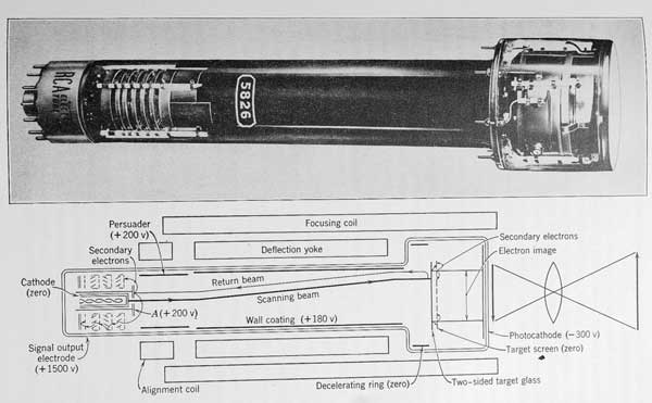
THE IMAGE ORTHICON A giant improvement was made when the image orthicon was first publicly demonstrated in October 1945 and used for TV pickup at the Army-Navy football game later that year. (29) This device is about 100 times more sensitive than the iconoscope. The image multiplier section of the tube provides a gain of 5. The signal multiplier at the tube base, utilizing a series of secondary emission rings, increases that by a factor of 20. (30)
According to my 1952 Allied Radio Catalog, this exotic tube cost nearly as much as a new car at that time. The IO camera was typically equipped with a lens turret having lenses ranging from 35 mm to 13 inch. Optical focusing was accomplished by a knob on the side of the camera which moved the pickup tube assembly with respect to the lens. The operator was provided with a headset which fed program sound to one ear and studio direction in the other. (31) And finally the operator had a CRT view-finder for more effective use under all conditions. This first IO camera, the TK-10 incorporating a type 5655 image orthicon, became available in late 1947.
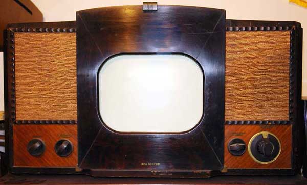
THE 630TS On September 17th, 1946, RCA introduced the first post-war TV. RCA Service Data-1946 No. T1 explains: “Model 630TS is a thirty-tube, direct-viewing, 10” table model Television Receiver. The receiver is complete in one unit and is operated by the use of seven front-panel controls. Features of the receiver include: Full thirteen channel coverage; F-M sound system; Improved picture brilliance; A-F-C horizontal hold; Stabilized vertical hold; Two stages of video amplification; Noise saturation circuits; Three stage sync separator and clipper; Four mc. band width for picture channel, and reduced hazard high voltage supply.” The set cost $375, more than a typical months’ pay for many folks. (32) Manufactures paid royalties to RCA to put their name on similarly designed television receivers. These sets were immensely popular. About 1947, I remember watching Texaco Star Theater, along with half of my suburban NY neighborhood, on one of these 10-inch sets. It never occurred to us that the picture was too small.
COLOR TELEVISION RCA’s prototype fully-electronic color camera employed special tinted semi-transparent mirrors to separate the image into red, green, and blue components, each color scanned by its own image orthicon.
At the receiving set, the three primary color signals are recombined in the tri-color picture tube. On October 10th, 1949, RCA demonstrated to the FCC their all-electronic, compatible color system. That same day, the TV show, Kukla, Fran and Ollie, became the first regular television program to be seen simultaneously in color and black-and-white. (33) The first shadow-mask tri-color tube was demonstrated in the lab in the fall of 1949. (34)
RCA having invested 50 million dollars and two decades of effort was finally able to make money on TV by 1949. They owned most of the patents and had the cameras, studio equipment, transmitters and receivers; all sought after by eager TV stations and viewers alike. David Sarnoff’s multi-million dollar gamble finally paid off.
REFERENCES 1. Eugene Lyons, David Sarnoff, 1966, pg. 209.
|
