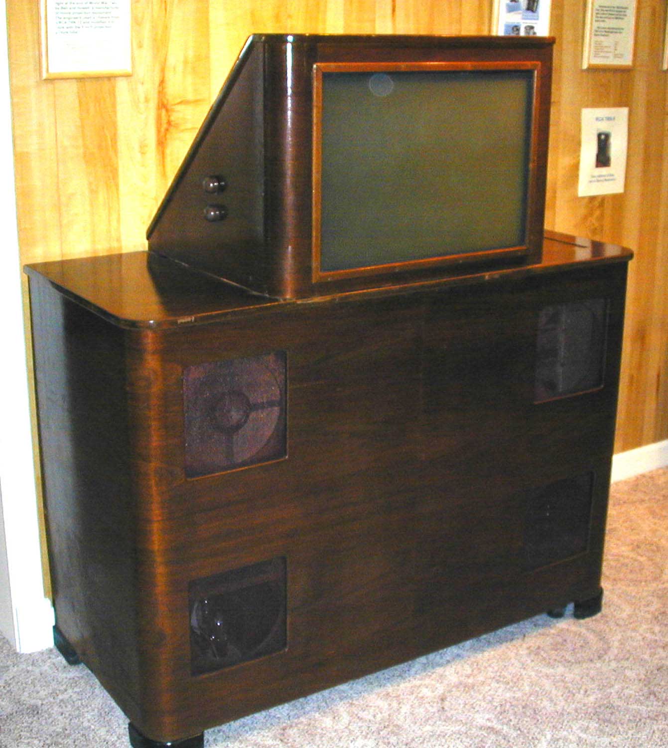
Early Electronic Television
Bell & Howell Projection Set

(click on picture for high resolution image)
|
Screen Size |
24 inch (5 inch CRT) |
|
Year Made |
1944-45 |
|
Quantity Manufactured |
1 |
|
Original Cost |
? |
|
Number Still in Existence |
See Early Electronic Database |
|
Cabinet |
Original Finish |
|
Chassis |
Restored |
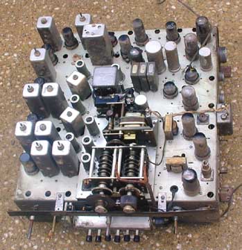
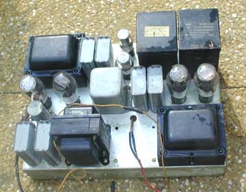
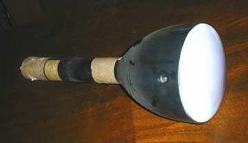
The set is a prototype, with pencil marks all over the chassis. In
fact, the RF chassis is actually a prewar RCA TRK-12 chassis, with
the original IF stages left as they were, but the rest of the
circuitry removed. A new tuner and other circuits were added.
RCA provided developmental tubes, including the CRT, to Bell and Howell
and other manufacturers, who also produced prototypes using these
components. RCA published details of a prototype projection system in 1945.The
optics and CRT in that article look much like those in this set. Here are more details.
This set has a 20 inch screen. It has a 5 channel pushbutton tuner.
Two of the buttons are marked with WBKB and WDLM. WBKB was a TV
station which went on the air in 1939. WDLM was a FM radio station,
which went on the air in 1943. The tuning dial is marked with
channels 1- 6 and FM radio at 88-108.

This is the CRT assembly. A parabolic mirror is in the bottom the of
black round container. It reflects the light from the CRT screen up
through a clear plastic area (around the neck, next to the yoke) to a
mirror in the top of the cabinet. In front of the CRT is the
horizontal sweep section. |
|

The CRT is a RCA developmental tube
#C7549D, similar to the 5TP4, but with a lower deflection angle. |
|

This is the high voltage (EHT) power supply. It contains a two high
power RF oscillators, one with a single rectifier to supply to focus
voltage, and the other with 2 rectifier tubes operating as a voltage
doubler, producing probably 25 kv. The rectifier tubes are RCA
developmental number R6794A. The copper loop is the filament
winding for one of the rectifiers. Notice the large glass insulator
in the middle. |
|

This is the horizontal sweep chassis. It uses a RCA developmental
tube # A4412, which looks like a 6BG6, as the horizontal output.
Another tube, marked 343-L, is the damper. |
|

This is the low voltage power supply chassis. It contains 4 rectifier
tubes and three voltage regulators. |
|

This is the RF chassis. It contains a motorized tuner covering 45-135
mHz. It has an FM audio detector, since the FCC changed TV sound from
AM to FM in 1941. The chassis is from an early electronic RCA TRK-12. The
components on the far left side are original RCA parts, while
everything else was added by Bell and Howell. |
|
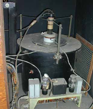
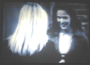
After cleaning the lenses, the picture is now relatively clear.
However, the lens and mirror are diffusing the light and making the
image fuzzy. We will eventually get the mirrors resilvered.

Invisible text to format smartphones. xxxxxxxxxxx xxxxxxxxxxxxxxxxxxxxxxxxxxxxxxx xxxxxxxxxxxxxxxxxxxxxxxxxxxxxxxxxxxxxxx xxxxx xxxxxx xxxxxxxxxxxxxxxxx xxxxxxxxxxxxxxxx xxxxxxxxxxxxxxxxxxxxxxxxxxxxx
|