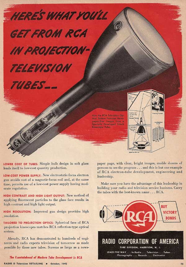
Early Electronic Television Bell and Howell Projection SetCabinet. (pictures). The cabinet is in fair condition. We will attempt to touch it up. The CRT is in a wooden cylindrical case with a curved mirror in the bottom. Light is reflected from the CRT by the mirror up through a plastic ring around the CRT, then to the mirror on the top of the cabinet. The CRT is a 5 inch RCA developmental tube. Though it is similar to the 5TP4, which was introduced in 1946 and was used in many early projection sets, this tube is about two inches longer, uses a lower deflection angle, and has a different base. Here is a 1945 ad for the tube: Chassis. There are five chassis: Low Voltage Power Supply, HV Power Supply, Horizontal sweep, Audio/Video, and Audio Power Amplifier (which is missing). Each will be cleaned with water and a mild detergent using soft brushes to get into small places. Then, all paper capacitors will be replaced with modern ones (see the procedure for this). Each electrolytic capacitor will be tested for leakage and capacity. If bad, new electrolytics will be installed inside the old ones. Low Voltage Power Supply Chassis: (pictures). This chassis is in excellent condition. It contains the low voltage supplies for the TV chassis. Since we have no schematic diagram of this chassis, the first step is to trace one. All but one of the electrolytic capacitors are oil filled, and are good. The remaining one has been rebuilt. In order to assure that the sweep circuits are operating before high voltage is applied to the CRT, there is a 30 second time delay relay in one section of the power supply. It was defective, but we were able to repair it. This chassis is now working. High Voltage Power Supply: (pictures). This chassis is in excellent condition. It contains the HV (EHT) and focus voltage supplies for the CRT. It contains a two high power RF oscillators, one with a single rectifier to supply to focus voltage, and the other with 2 rectifier tubes operating as a voltage doubler, producing probably 25 kv. The rectifier tubes are RCA developmental number R6794A. The copper loop is the filament winding for one of the rectifiers. Notice the large glass insulator in the middle. This chassis contains no paper capacitors, only mica and oil filled military capacitors. For this reason, we are not rebuilding any of them. The filter capacitors for the focus voltage are mica also. After getting the power supply working we applied power and we now have about 20 kv for the high voltage and 2 kv for the focus voltage. After attaching the CRT the high voltage dropped to 10 kv, and the picture blooms when the brightness control is advanced. There is some sort of problem in the voltage doubler. It turns out that 2 out of 3 of the rectifier tubes are bad. I am attempting to find out what they are - the ones in this set are RCA developmental tubes. If anyone has information on these tubes, please contact me. I have been told that this is a 8013. I have found a couple of sources for it, and will order some. For now, I have soldered 3A3s in. The recommended voltages for the 5TP4 are 27 kv on the anode, and 4-5 kv on the focus grid. I have about 22 kv on the anode, and 4 kv on the focus grid. I will have to do some more work to find out why the anode voltage is low. There are several possibilities. The 3A3 might not work properly as a replacement rectifier; the HV capacitor in the voltage doubler might be bad; or there might be a problem in the 6Y6 circuits that generate the RF. I discovered that the set has a "service" switch on the HV power supply that reduces the high voltage to 22 kv for testing. Putting it in the "operate" position and replacing the 3A3s with 1B3s resulted in 27 kv on the anode. The picture is now very bright and crisp. Horizontal Sweep Chassis: (pictures). It uses a RCA developmental tube # A4412, which looks like a 6BG6, as the horizontal output. Another tube, marked 343-L, is probably the damper. This chassis has no paper capacitors, and when I powered it up, it worked fine. Audio/Video Chassis: (pictures). This chassis is in excellent condition. It contains the RF, IF and sound and vision detectors. It contains a motorized tuner covering 45-135 mHz. It has an FM audio detector, since the FCC changed TV sound from AM to FM in 1941. The chassis is from a prewar RCA TRK-12. The components on the far left side are original RCA parts, while everything else was added by Bell and Howell. The chassis also contains the vertical sweep circuitry. Tracing the circuit diagram has been a chore. It is very complicated, with 6 tubes used in the sync circuits alone. There are many bias supply voltages, and at least 6 different B+ lines. I have rebuilt the paper capacitors in the vertical sweep circuits, and now have that section working. The tuner and IF sections seem to be fine, and I have video at the output of the detector. I am now rebuilding the capacitors in the video amplifier section. There is a problem with the AGC, which is stuck at -30 volts. I have finished getting the video amplifier and sync circuits working. This set is very complicated, with 3 video amplifier tubes, a DC restorer, and 6 tubes in the sync separator/phase detector circuits. The AGC is still a problem. Several resistors in the circuit have been clipped loose, and trying to figure out how it works is difficult. I have got the AGC working, after experimenting with placement of the resistors. The video circuits now work properly, and I have a good picture on the CRT. The audio section also works. Next I will debug the motorized tuning. Now that I can critically look at the picture, I notice that it is quite noisy. I will go back and check the RF and IF sections to see if there is a problem. I installed a pot in the AGC circuit to adjust the voltage. This way I can set it for best results. Today I fixed the motorized tuning. It uses a small motor with a number of relays and microswitches, together with the pushbutton assembly to tune. Depressing a pushbutton activates a small solenoid (there are a total of 6, one for each button), which engages a mechanism that tells the motor where to stop. These solenoids are fed through a very large (100 watt) resistor, which was open. I calculated the current flow through the resistor, and determined that it actually dissipated the full 100 watts when the solenoid was activated. The only purpose for the resistor is to drop the AC line voltage to 12 volts for the solenoid. It is amazing to me that this set was designed to require 100 watts of power just to operate the motorized tuning device. A small stepdown transformer would have worked much better. This set has a very early form of AFC. The circuit works properly.
|