Early Color Television Field Sequential Sync and Color Bar GeneratorIn order to operate the surviving field sequential receivers and monitor, we will need a sync generator that creates the timing pulses for the CBS standard. The easiest way appears to use an EPROM programmed with one complete frame of sync information. In this way we can generate a waveform exactly like the original, including the color wheel sync signal. We also plan to make a camera. On this page we will give the technical details of the project and our progress. The CBS standard had 24 complete frames per second. Each frame was made up of 6 fields, 2 for each color, and each having 202 1/2 lines (interlaced). The field rate was 144 Hz. The sequence was red odd lines, blue even, green odd, red even, blue odd and green even. Each complete picture was 405 lines, and the horizontal (line) scanning rate was 29,160 Hz. Equalizing pulses were inserted in the vertical (field) blanking interval. To synchronize the color wheel, a pulse was inserted between the 2nd and 3rd equalizing pulses at the beginning of each red field. We are using a 128k x 8 bit EPROM to store the waveform. One frame has 1215 lines (202 1/2 x 6). The 128k EPROM has 131,072 bytes, or 107.87 per line. So, we will use 106 bytes per line (we need an even number for accurate spacing of the equalizing pulses), and use 128,790 bytes of the EPROM. This should allow us to reproduce the horizontal (line) sync pulse fairly accurately, and also allow us to put a color bar pattern in the EPROM. The design consists of a clock incrementing 5 four bit counters in series to make up a 17 bit counter. The counter is then connected to the inputs of the EPROM. The counter is wired to start at 2280. When it reaches 131,072, when the frame is complete, the counter is reset to start the cycle again. The horizontal (line) scanning rate in the CBS system is 29160 Hz, or
34.2 microseconds. Since there are 106 bytes per line, the clock rate
would be 34.2/106, or .3226 microseconds, which equals 3.09 mHz. Two versions of the generator will be built. The first will be for use with the Gray Research monitor and the surviving field sequential receivers. This EPROM will be programmed as follows: bits 0-5 video, bit 6 composite blanking, and bit 7 composite sync. This allows for 64 levels of video luminance, which will be adequate for the color bar pattern. The top two thirds of the test pattern will be color bars, and the bottom third will be a grey scale. The second version will be used with a color camera (more on this later). In order to synchronize the color wheel, the EPROM will be programmed with a 48 Hz sine wave in phase with the frame scanning, which will be amplified and used to drive a synchronous motor connected to the color wheel. This EPROM will be programmed as follows: bits 0-5 48 Hz sine wave, bit 6 composite blanking, and bit 7 composite sync. A color sync (red field) pulse will be superimposed on the 48 Hz sine wave. In order to create the data file used by the EPROM programmer, we have written a Visual Basic program that generates the proper values for all 128,790 bytes. As we test the waveform we can easily change the contents of the file, and therefore the EPROM, to correct mistakes and refine the position of the various signals. One thing will have to be determined by trial and error. Since the color filters on the monitor have different light transmission values, the luminance of the three color video signals will have to be adjusted to obtain a good white balance. After we have the unit completed we will experiment with this. The eprom has been successfully programmed and tested. A few remaining things need to be added. Then, a printed circuit board will be made and several units made.
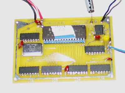
The design has been completed and tested, and a printed circuit board has been made. |