
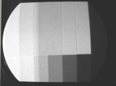
Early Color Television Gray Research Monitor RestorationThis monitor was made for the CBS field sequential color system, which has 405 lines, with 24 complete frames per second (6 fields, 2 per color), and a horizontal (line) scan rate of 29,160 Hz. Here is technical information on this monitor. In order to be able to view pictures on this monitor, we will have to make a signal source. At first, we will build a color bar generator. Cabinet. (pictures) The cabinet is in decent condition, and will only require a paint job to make it perfect. I have located a company that can do the wrinkle finish, and will have this done soon. The color wheel, motor, and lens are missing. Fortunately, we have a wheel and motor that will probably work, from another CBS color wheel assembly. The lens appears to be a standard oil filled magnifier, sold to enlarge the size of pictures on TV sets of the time. We will look for one that is the proper size. The CRT is a 10FP4 mounted in a metal shield. Chassis. (pictures) There are two chassis in this set, the Main Chassis and the Motor Control Chassis. These chassis are in good condition. Each chassis will be cleaned with water and a mild detergent using soft brushes to get into small places. Then, all paper capacitors will be replaced with modern ones. Each electrolytic capacitor will be tested for leakage and capacity. If bad, new electrolytics will be installed inside the old ones. We have no technical information on this monitor, so we will have to trace the circuit diagram. John Folsom and Ed Reitan are sending schematics of similar devices that may be helpful Main Chassis: This chassis has video, audio and composite sync inputs. The video is amplified by 3 stages, then fed to the grid of the CRT. Sync is amplified by 2 stages, then fed to the vertical (frame) and horizontal (line) oscillators, which feed output stages. A damper is employed in the horizontal (line) deflection circuit. A voltage doubler is driven from the flyback (line output) transformer, supplying about 12 kv to the CRT. The audio is amplified by a single stage, then fed to an output amplifier and then to the speaker. This chassis has been modified, and several parts removed, including most of the connectors on the rear panel and the contrast control. Many of the wires have been cut, and it appears that someone attempted to reconfigure it to work on the NTSC standard. We have restored most of the wiring and have gotten the power supply working. Several parts in the sweep sections are missing, including the vertical linearity control, the vertical output transformer, and horizontal drive control. After we have replaced the capacitors we will determine the values of the missing parts by trial and error. We've made a new mount for the horizontal size control, and have determined that the horizontal drive control is around 2 megs. The horizontal oscillator appears to work properly now. The horizontal output stage has some sort of problem, however, since the anode voltage at the CRT is only about 6KV, and drops to 2KV at times. After replacing the capacitors in the vertical sweep section, and installing a vertical output transformer from an early RCA set, the vertical deflection appears to work properly. John Folsom has located a complete technical manual for the monitor, and has forwarded a copy to us. I'll wait until we get it to continue with the restoration. Several electrolytics have overheated as we have been testing the monitor. They will be replaced. All of the paper capacitors have been replaced, and the missing components have also been replaced. The monitor now seems to operate properly, other than a problem in the vertical sweep. There is insufficient height, and foldover at the top of the screen. I will experiment with other output transformers. The problem was a bad vertical oscillator tube. Now that the color bar generator prototype is working, the monitor now displays a black and white grey scale pattern. The pattern is made up of color bars on top and grey scale on the bottom. There is still a problem with the horizontal sweep - notice the vertical bands to the right of the second color bar. There are a few more things to be done on the monitor chassis: Shaft extensions for some of the controls, a flexible shaft to bring the contrast control to the front panel, and installing a recessed Cinch Jones connector for cable to the motor control chassis. Now I am working on the motor and wheel assembly. The CBS receiver parts we had previously acquired, and thought were from a home receiver, are actually from a Gray Research monitor. The motor fits perfectly on the motor mount frame.
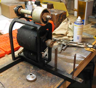
At the top is the wheel shaft (the wheel mounts at ther rear) and the alternator. The sprocket in the foreground will be drilled out to fit over the wheel shaft next to the alternator. Then a belt will be installed. The new belt has arrived and has been installed. The motor assembly has been put back in the cabinet. We now have color pictures on the screen, though the motor sync doesn't yet work.
Motor Control Chassis: This chassis has the circuitry to keep the color wheel motor synchronized to the vertical sync pulse. CBS inserted a special pulse in the vertical blanking interval at the beginning of the first red field. The pulse is extracted and applied to a circuit that compares it to a signal from an alternator mounted on the motor shaft. The motor speed is varied until the pulse and alternator signal are in phase. Many parts have been removed from this chassis, including all the connectors, a relay board, the electrolytic capacitors, and the saturable reactor, the device which controls the motor speed. We have replaced the electrolytic capacitors and the power supply is now working. The rest of the circuitry now works, and a control voltage is being generated by the pulse comparator. However, we have been unable to make a standard tranformer work as a saturable reactor, and therefore can't vary the motor speed with the control voltage. We are pursuing two approaches to make the motor sync work. First, we will try a triac as the speed control device. It should be simple to interface the triac to the control voltage and thereby control the motor speed and attain color wheel sync. The second approach is to have a replica saturable reactor made. John Folsom has a similar reactor in his CBS color set. From measurements taken of his reactor, Ed Dinning thinks he can duplicate it. I put a strobe disk on the motor and discovered
that it is a synchronous motor, not an induction one. The 1800 RPM should
have been the clue, since induction motors are all less than than,
something like 1750 rpm. Also, the capacitor is required not only during
startup but also while running. That explains why I couldn't vary the
motor speed with the transformers I was using as saturable reactors. After much experimentation with using filament and audio output transformers as saturable reactors, I have concluded that the approach won't work. Eventually I will have Ed Dinning attempt to build a replica reactor, but for now I have designed a circuit using a 6 amp Triac driven from the 6AG7 reactor driver tube. The circuit works perfectly, and the color wheel now stays in sync. The start winding on the motor is bad, so I must spin the wheel to get it started. I have a new 1650 rpm motor which I will try. Unfortunately, the new motor rotates the wrong direction. However, I was able to repair the old one. The centrifugal switch that engages the start winding was dirty. After cleaning it, the motor starts nicely.
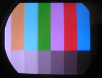
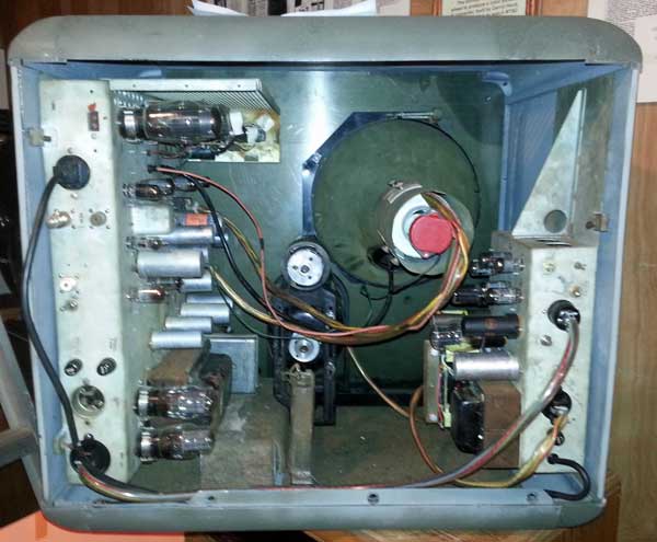
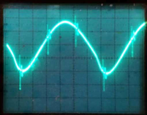
Here is a photo from the screen after the color sync was repaired. In June of 2008 Cliff Benham came to the museum to attempt to get the replica saturable reactor, made by Ed Dinning from the original CBS specifications, to work. After several hours spent improving the operation of the motor and the color wheel, Ed was able to get the reactor to work. The anti-hunt circuit was missing, and after installing it, the wheel synchronizes perfectly. Many thanks to Cliff for his work on this unit and on our Col-R-Tel and Colordapter. In 2010, Cliff did extensive research on finding the best color filters for use with the 10FP4, and made a new wheel for the Gray Research monitor. The result was a much superior picture. In October of 2013 we went over the monitor to make sure it was properly documented and made several changes to the motor control chassis based on new information we found. The result is a much more stable and reliable color sync, with no hunting. Here is a photo of the rear of the monitor after this work: In July of 2014 we explored the purpose of J4 (test point) on the motor control chassis. Two capacitors superimpose the sine wave from the generator and the vertical sync pulse. This test point was used to set up the phase and anti-hunt controls.
I determined that the proper setup involves moving the vertical pulse to the bottom of the sine wave, then adjusting the hunt control to minimize back and forth movement of the pulse. This works much better than just playing with the controls while watching the screen for the proper wheel sync.
|