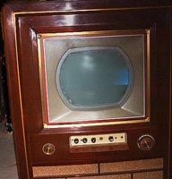
THE SETHorizontal OscOut of a total of thirty-six tubes, the entire CTC-2 chassis uses only five octal tubes. They are the 3A3 high-voltage rectifier, 6BD4 high-voltage regulator, 6AU4 damper, and, of course, the 6CD6 horizontal deflection amplifier.All the rest are 7- and 9-pin miniature tubes. All, that is, except the horizontal oscillator and control. That's the fifth octal, a 6SN7. One might think this dual-triode workhorse would have been obsolete by 1954, supplanted in new designs by its 9-pin miniature replacement, the 12AU7. CBS's 19-inch CTC-2-like clone, the model 205, used a 12AU7 for its horizontal oscillator and control. Even in 1955, which brought the CTC-4 reduced-tube chassis, RCA still used a 6SN7 for the horizontal oscillator and control. Now I'd like to have an answer to the obvious question, but I don't. Why this workhorse circuit, the subject of this page, survived for so long in new RCA designs using a dated tube is a puzzle. But there it is. Maybe some of you have a clue. [from email 3-2-2006: I think the reason RCA stuck with the 6SN7 (and not just in color sets -- they used it in lots of B/W sets in that era) was that while its characteristics are very similar to the 12AU7, the 6SN7 has considerably higher plate dissipation due to its larger size -- 5W per section as opposed to 2.75W for the 12AU7. In an audio amp, running at very low power, it would make no difference, but a horizontal oscillator can push the tubes a lot harder, and the operating environment (right near hot things like horizontal output tubes and the like) is a lot more stressful. There were miniature tubes designed for this service, the 6CG7 and its later version the 6FQ7 (an RCA favorite in the 60s), all with higher plate-dissipation ratings than the 12AU7. Ted Zateslo Tallahassee, FL ] We do know that the 6SN7 stubbornly clings to life -- it's still manufactured. In 1999 I succumbed to curiosity and bought a new one from AES for a few bucks. A Sovtek. I eyeball the internal leads as being about 20 percent longer than my "reference" RCA 6SN7GTB, and it had a date code of early 1990. Clearly relabled as a 6SN7, it was made in Russia as a 6H8C. But to the circuit. The original RCA 630TS horizontal oscillator and control system from 1946 was called Synchro-Lock, and it used a 6K6 as a hartley sine-wave oscillator running at the horizontal line frequency, with a 6AC7 reactance modulator and a 6AL5 sync discriminator circuit backed up to the hartley through its transformer, with 1/2 a 6SN7 as the horizontal discharge and driver -- that's a mouthful and that's the point. It was soon simplified and morphed into Synchro-Guide. The CT-100 version is shown in its RCA-schematic incarnation next. 
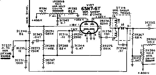
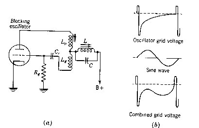
The transformer used for positive feedback from plate to grid does not have the conventional isolated windings. It's more like an autotransformer. The grid-leak capacitor (C129 Sams, 2C236 RCA, Cc at left) charges rapidly when grid current flows (the retrace period) and develops enough bias to cut the tube off for the trace time. There's a slug in the plate winding to set the basic frequency of oscillation. At the junction of the plate and grid windings, a third inductor is added and an external 0.01 uF cap is strapped across it (C130 Sams, 2C234 RCA, C at left). This forms a resonant circuit that rings when blasted by the brief plate current pulse (the tank is in series with oscillator B+). This horizontal-rate 'Sine wave' voltage combines with the 'Oscillator grid voltage' waveform to sharpen the waveform slope as it rises toward the conduction point. There's a slug in the tank inductor that varies the waveshape for an optimum slope. The result is greater noise immunity. Any noise would need to overcome the more negative 'Combined grid voltage' bias (more negative at any instant, particularly during the period just before conduction). Frequency control of a blocking oscillator is fairly simple. To increase the frequency, for example, decrease bias on the grid. It will then take less time for the grid capacitor to discharge and drive the tube into brief conduction again. To accomplish frequency control, part of the horizontal drive signal is coupled (see RCA schematic, above) from "D" on the blocking oscillator transformer, through 150-kohm resistor 2R273 and 82-pF cap 2C246, to the grid of the control tube. A positive horizontal sync pulse is combined with the oscillator signal and the two affect how hard the control tube conducts. Note in the simplified schematic (below) that only when there is a sync pulse (labeled "voltage input") can the control tube conduct. The harder the control tube conducts, the less negative the oscillator grid voltage becomes. A greater positive drop across cathode resistor (2R287 above, R3 below) is filtered and fed to the oscillator grid through resistor 2R275 above (or below, directly). And finally, to keep the control tube cut off until a positive sync pulse arrives, the negative bias on the oscillator grid can be used. Resistor 2R289 does that job in the CT-100. Updated 16-July-2000; 09-April-2005; 04-April-2006.
|