
| The Set: Pete Deksnis's Site about the CT-100 Restoring a Vintage Color Television Set |
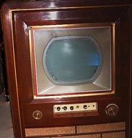
THE SET
Power Ssupply
A low-voltage power supply, as opposed to the high voltage (19.5 kV) flyback supply, supplies six different working voltages to circuits in the CTC-2 chassis: 380, 375, 285, 275, 175, and a negative 30 volts to bias the 6CD6 horizontal output tube.
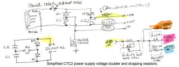
A voltage doubler and dropping resistors make up the prime elements of this relatively simple supply. The doubler is fed by a non-center-tapped secondary winding of the power transformer.
My hand sketch includes a voltage doubler in simplified form (except that I drew the diodes upsidedown!). When the polarity of the ac input is negative on the right AC IN input terminal, current flows through M1 and charges C1. During the next half cycle of the ac input, the left-hand AC IN terminal is negative which charges C2 through M2. Since C1 and C2 are in series, and series aiding at that, the rectified output is twice the ac input.
Yellow highlights the equivalent point on the simplified schematic and on the more traditional layout found on commercial schematics of the CTC-2 chassis. Three hundred and eighty volts is the basic doubler output from which all but one (175) of the other five voltages are derived.
Where 380 represents the total voltage across C1 and C2, the 175 is the voltage across C1 alone.
A 30-volt drop across a filter choke serves as the negative bias supply voltage.
Notice how the 380-volt doubler output is applied to the series dropping resistors. I color-coded the four main voltages here and where they are found on my working copy of the main schematic.
This is, by modern switching power supply standards of course, a very inefficient way to develop power supply voltages. A great deal of power is wasted in the form of heat. The designers extended the ballast tube from the rear of the chassis where heat dissipation is more easily achieved. I recall that it runs quite warm in spite of its location.
My plan for the power supply is to bring it up slowly with a variac after voltage has been carefully applied to individual circuits with an external supply. Some functions such as the audio chain, video if, and tuner will be made operational first using an external power supply.
I will then check the power supply by running it unloaded. This is probably safe from an equipment point of view since there was no delay applied at start-up to this supply during normal, consumer use. The rectifiers are solid state selenium. So, turning on the power switch placed the full unloaded voltage across the filter caps until tube filaments ramped-up to operating temperature, which resulted in tubes drawing plate current, which meant increased current through the ballast resistors, which increased the voltage drop across them, which lowered power supply bus voltages to operational levels.
---- ----
The 375-volt bus distributes power to eleven parts in the CTC-2 chassis as annotated by Sams Photofact set 252, folder 11, dated 9-54. Five of these loads (shown with an asterisk) are incorrectly shown to be connected to the 380-volt bus.
R11 A 15K red screen control
R13 A 15K grn screen control
R13 B 15K blu screen control
R93 4.7 meg* agc circuit
R95 820K* agc circuit
R125 3.9K H sync sep plate load
R144 4.7K V osc plate supply
R149 5.6K V out plate supply
R170 56K* H afc plate supply
R174 68K* H osc plate supply
V11 6AN8 screen grid* pin 7
Last Updated on 9-13-99.