10-3-99 I recently found a hand-written 4-digit number
inside the envelope
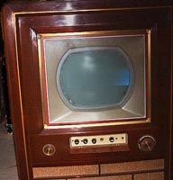
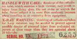
of my 15GP22 tricolor kinescope. The number, 6255, matches the serial number on this label RCA glued to the outside of the tube. A wealth of new/old information about the design, development, and construction of early color picture tubes has resulted. Sources include both fellow restorers, the Internet, and my personal experience adjusting and viewing old 6255 for three years between 1963 and 1966.
Here are some facts and some speculation I've found interesting. Please offer corrections and comments via e-mail.
The earliest color television designs did not use a color picture tube. The early '50s CBS approach was to use a b&w kinescope and put spinning color filters between it and the viewer, with identical
primary-color filters
spinning in front of a black and white camera.
This was the basis of an FCC-approved CBS color system, which broadcast programs occasionally during a few months in the summer of 1951. But nobody saw those shows because (1) nobody had a color TV because (2) nobody bought them, because (3) CBS-Hytron only manufactured a handful of sets (the model 12CC2). It is shown here as it appeared in a 1951 ad. They were sold almost nowhere (Gimbels on 34th Street in Manhattan had some), and (4) the system broadcast a 405-line picture, whereas tens-of-millions of b&w sets in the US received only 525-line pictures. I was an eleven year old kid that summer and distinctly remember "seeing" a CBS color broadcast from WCAU-TV in Philadelphia on the family's 16-inch Silvertone. I was awestruck by the color transmission, but all I saw was a severely out-of-sync
display
akin to a scrambled cable channel today. Apparently only two, maybe three, sets survived a "buy-back" by CBS who then reportedly destroyed them.
That's gotta have been the biggest sucker-punch foisted on the American public to that time. Probably held the honor until it was bested by Electric Heat in the '60s.
To be fair, that color system, had it been given the opportunity to develop into an all-electronic system, would probably still have resulted in the ubiquitous presence of color TV we experience today, but it would have happened much, much sooner. It took ten years of losing (?) money before compatible color TV took off about 1963. An all-electronic CBS color system would have used a color picture tube much simpler in design and easier to manufacture than the RCA 15GP22. But then again, the world would soon drop the lower-resolution 405-line system, as is evidenced by the British, who switched, although slowly, from their
405- to a 625-line
system. We would have been stuck with an albatross, albeit a colorful one.
Anyway, the first all-electronic approach taken by RCA used three separate picture tubes. Each displayed only one of the primary colors. All three images were combined, using either dichoric mirrors or projection, on a common screen. They were big, bulky, bastardous things that worked, but in that era, could not have been scaled, in either economy or size, to fit into a living room.
It was clear that a b&w style picture tube that displayed color would be needed if color television were ever to become a reality and commercial success.
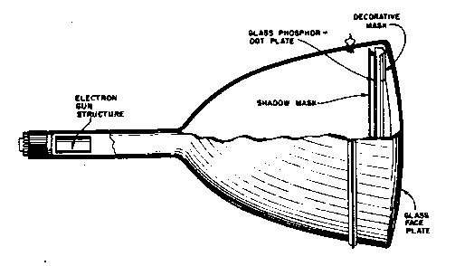
The tricolor picture tube became that vehicle (1953 RCA illustration below). As early as 1950, RCA demonstrated an all-in-one color picture tube. It had four basic parts -- a flat, GLASS PHOSPHOR-DOT PLATE (the viewing screen), a SHADOW MASK, an ELECTRON GUN STRUCTURE (with 3-guns), and an envelope that consisted of a neck, glass funnel, and GLASS FACE PLATE. In addition, the production tricolor picture tube included a DECORATIVE MASK that surrounded the glass phosphor-dot plate.
Television viewers see the decorative mask encircle a recessed color picture as they look through the glass face plate. It's a bit like looking through a window. You view a 15GP22 by looking into it. It's different -- the picture appears to come from inside the tube. I recall the effect well: it's more pronounced when viewing the tube at close range, as when making adjustments.
Modern tubes have the phosphor deposited directly on the inside of the glass face plate, so we are accustomed to a picture that appears to come from the front of the tube. That process was first used by CBS, and RCA followed suit by the end of 1954 with its 21AXP22.
At the end of 1953, so my information goes, CBS-Hytron developed an NTSC-based console using a developmental 15GP22. Later, when the first CBS model went on sale, they used their own version of the RCA tube, the 15HP22, the so-called CBS-Colortron. It was directly interchangeable with the 15GP22, but theirs was a much improved design.
Unlike RCA's planar shadow mask and separate phosphor dot screen, the CBS tube use a curved shadow mask, or aperture mask as they seemed to call it, that matched the curvature of the face plate, and so they could deposit the phosphor directly on the face plate. There is a collector on the East coast who has a 15HP22 and who has had it operating, although not recently. When they are examined side-by-side, the two tubes are distinctly different -- the 15HP22 does not have an internal decorative mask. But both do use electrostatic convergence and so have the fourth element.
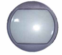
An October '99 photo of 15GP22 s/n 6255 shows just the DECORATIVE MASK and the GLASS PHOSPHOR-DOT PLATE. Flairs on the thick but crystal-clear, rounded GLASS FACE PLATE give the illusion of roundness to the flat, glass phosphor-dot screen.
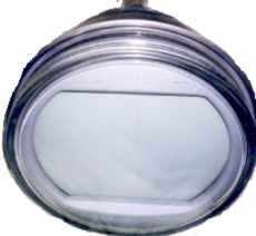
A picture taken at an angle reveals how thick the decorative mask actually is. The Z-axis dimension, by inspection, is greater than 1/2-inch.
The concept of turning a tiny trio of phosphor dots (each one a primary color) into a viewing screen by duplicating the tri-dot pattern hundreds of thousands of times on a piece of glass, was well established. It just wasn't easy to do.
Each electron beam is vectored at an angle of about one degree as it converges with its mates at the shadow mask. Beams then diverge enough to accurately strike their respective phosphor dots.
Problems included the quantium efficiency of the phosphor. For a given electron beam, the blue phosphor would glow about three times brighter than the red phosphor. Green was somewhere in the middle. Persistance was a problem. The blue phosphor used in 1950 would glow for a longer time than either the red or green phosphor. The red wasn't red enough so a color filter was once added. A blue object moving across the screen left a blue trail.
Finally, by 1953 the red phosphor is redder, and brightness problems are overcome by driving the red phosphor harder. Blue phosphor persistence is improved. All dots are metalized to eliminate ion traps and help direct light forward, toward the viewer. But getting 585,000, 0.0136-inch-in-diameter phosphor dots on (1) a viewing plate (glass phosphor-dot plate) suspended behind (2) the glass face plate, with (3) a shadow mask suspended about 1/2-inch behind the glass phosphor-dot plate, was no easy matter. A shadow mask is a thin sheet of steel (Invar?) with one 0.009-inch hole for each phosphor dot trio on the viewing screen. For the 15GP22, a shadow mask with 195,000 holes is used.
Apparently, each 15GP22 was manufactured using the following process.
Replace an electron gun with a light source and expose a sheet of photographic film located behind the shadow mask.
Use the developed film to make a silk screen.
Use the silk screen to deposit phosphor dots of ONE color on the glass phosphor-dot plate.
Expose a second piece of film through the shadow mask, but this time move the light source to the point-of-view of a DIFFERENT electron gun.
Make another silk screen and use it to deposit the second set of phosphor dots across the face of the glass phosphor-dot plate.
Repeat the process for the third and final electron gun and phosphor dot set.
THIS INVOLVED PROCESS ENSURED THAT the position of PHOSPHOR DOTS DEPOSITED ON THE GLASS PLATE HAD THE SAME MICROFLAWS AS THE SHADOW MASK THEY WERE TO BE USED WITH.
It was a very costly and difficult process, but it was necessary to ensure purity. If a hole in the shadow mask is misaligned, but for some reason the dots are not, the three electron beams passing through the hole may fall on other than their assigned dots. (For example, when the 'red' electron beam illuminates only the red phosphor, you see 'pure' red. If the red electron beam also strikes some of the green phosphor, you will
no longer see
pure red.)
So is my mystery solved? Did someone write the same serial number on the shadow mask assembly and the glass phosphor-dot plate? If so, was it because they are inseparable sets? Probably.
But I can't help wondering. Did it take the six-thousand two-hundred and fifty-fifth attempt to get a good shadow mask / phosphor-dot plate combo for the one-thousand two-hundred and seventy-third 15GP22 made?
A coating of conductive material on the inside and outside of each 15GP22 funnel acts as a small glass-dielectric capacitor to filter ripple occurring on the high voltage supply. There is not yet consensus among collectors as to whether some loss of the aquadag coating on the outside of the 15GP22 funnel is actually detrimental.
However, the coating on the outside of a 15GP22 can be replaced, and courtesy of Len Dole, here is an email of the procedure he used in March 2005 to apply a fresh conductive coating to an operational 15GP22.
Hi Pete,
I have successfully applied the new aquadag coating to the 15GP22. Following is the process I used.
1. Thoroughly clean the glass bowl of the 15GP22 with denatured alcohol. Make sure there are no loose bits of the old aquadag.
2. Mask off all areas of the glass that do not need to be coated. It sprays everywhere so good masking is essential. It is also a good idea to mask the neck and all the way around the face plate to prevent over-spray. It can be a bitch to remove if it gets where you don't want it to be.
3. I sprayed on four coats allowing 30 minutes between spray sessions. Allow a couple of hours for the new surface to thoroughly dry before removing the masking materials.
4. Finally I check with an ohmmeter to make sure that the material is indeed conductive - it is!
The spray on material can be obtained from Ladd Research Industries
www.laddresearch.com [1-800-451-3406]
at a cost of $20.00 plus shipping. There is plenty of the material in one spray can to do at least two tubes with up to four layers.
View a 51-year-old operational 15GP22 driven by a restored RCA CTC-2 chassis.
Comparison to modern high-definition television is shown.
Click here
.
Project to utilize full gamut of a 15GP22.
Click here
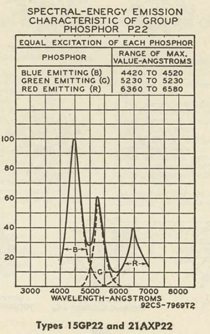
Published spectrum of 1953 NTSC P22 phosphors.
click here
.
Another step in the rebuilding process in the summer of 2008 was a success when Bob Galanter removed the base from a dud 15GP22 without damage. Note the extra insulation on the lead from the focus and the convergence electrodes, pins 6 and 13 respectively (focus voltage averages 3.5 kV and the convergence 13 kV). The stem with gun attached will be cut off. The old filament/cathode assemblies will be carefully removed by Bob, then the gun rebuilder in Georgia will mount [1] the new filaments, [2]cathodes, and [3] a new stem John Folsom was still able to have manufactured in 2008 by a company in New Jersey. Rebuilt guns with a new stem will be shipped from the gun rebuilder in Georgia to Scotty in Iowa where the rebuilding will occur. One of the last things Scotty will do is replace the original 15GP22 base on its newly functioning 15GP22.
Project to display full gamut of a 15GP22 at the 2007 ETF Convention
Click here
.
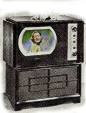 This was the basis of an FCC-approved CBS color system, which broadcast programs occasionally during a few months in the summer of 1951. But nobody saw those shows because (1) nobody had a color TV because (2) nobody bought them, because (3) CBS-Hytron only manufactured a handful of sets (the model 12CC2). It is shown here as it appeared in a 1951 ad. They were sold almost nowhere (Gimbels on 34th Street in Manhattan had some), and (4) the system broadcast a 405-line picture, whereas tens-of-millions of b&w sets in the US received only 525-line pictures. I was an eleven year old kid that summer and distinctly remember "seeing" a CBS color broadcast from WCAU-TV in Philadelphia on the family's 16-inch Silvertone. I was awestruck by the color transmission, but all I saw was a severely out-of-sync

 So is my mystery solved? Did someone write the same serial number on the shadow mask assembly and the glass phosphor-dot plate? If so, was it because they are inseparable sets? Probably.

