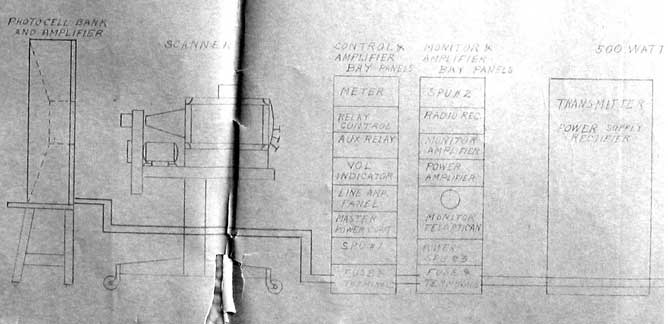
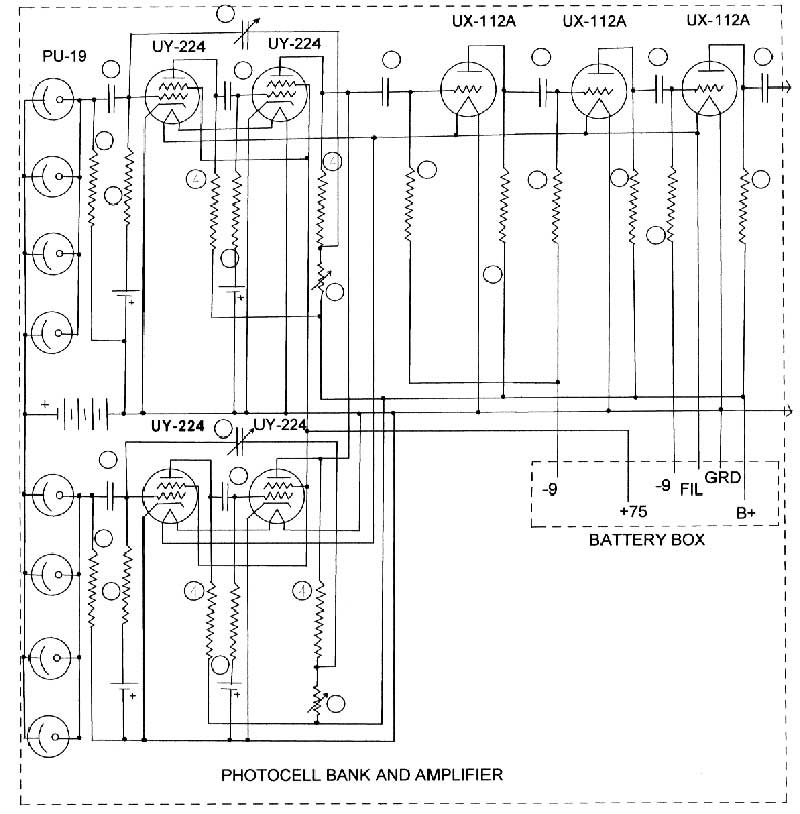
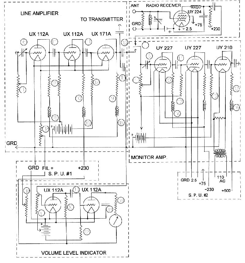
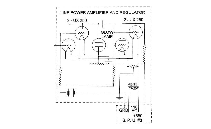
Mechanical Television CBS Mechanical CameraWe have acquired some papers from the estate of an engineer who worked for RCA in the 1930s on the development of television. In the papers was a blueprint of the TV system that RCA sold to CBS for use in their 60 line transmissions starting in 1931. Below is a block diagram of the system, copied from the blueprint. RCA used the same camera for their 60 line experiments. Because of the extremely poor condition of the print, it was not possible to scan or photograph the schematic diagram of the camera. However, we have copied the schematic and have posted it below. This is the only known surviving schematic diagram of a mechanical TV camera. The camera consists of several units. The first is the Photocell Bank and Amplifier, which contains 8 photoelectric cells and 7 tubes to amplify the signal. Notice that this entire unit is battery powered, to eliminate 60 Hz interference from the power line. Notice the high frequency peaking in the first two stages of the amplifiers from each set of photocells. The signal is then fed to the Line Amplifier unit, which uses three tubes to feed the transmitter. Also connected to the Line Amplifier is a Volume Level Indicator, which was used to set the video level. The adjustable capacitor at the input of the Line Amplifier provided additional high frequency boost. The Monitor Amplifier could be switched between two sources. The first is a direct feed from the Line Amplifier, and the second is from a single tube RF detector (Radio Receiver), which picked up a portion of the transmitter output. The monitor amplifier feeds the Line Power Amplifier and Regulator, which drives the neon tube.
|