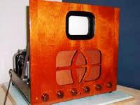
Early Electronic Television HMV 904 Restoration by Hugo HoldenThis set was sold to Hugo by the Early Television Museum. It is the third of these sets we had. One of the others was restored and sold to Tom Genova, and one remains in our collection. This set is complete except for the CRT. Hugo plans to restore it to working condition, and is paying particular attention to the appearance of the finished set. Here are two sets he has restored, an Andrea KT-E-5 and a Meissner 10-1153:
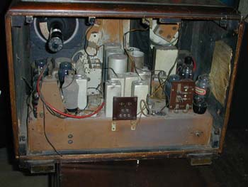
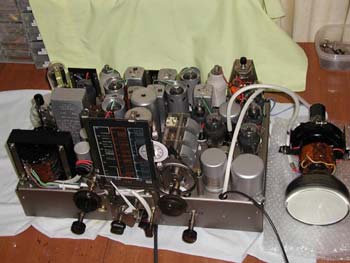
The HMV-904 Before Restoration Here is what he had to say when he started the restoration: March 2002: I've started on the set. It will require a complete re-build. Most of the insulation on the hookup wire is disintegrating, although you can still see the colours when the black soot is cleaned off. It probably lived in a coal mining town in the UK ! Once I've got the chassis extracted from the rest of the components so to speak I'll be able to have it re electroplated, it will need some glass bead blasting first to eliminate the rust. The same for the rest of the steel metalwork. Luckily the BA thread screws it uses are readily available new so I'll replace those with rust free ones. All of the coils seem basically ok which is great. I've got some rubber hookup wire much like the original to re wire it with. Most of the resistors are ok and most of the mica caps ok but the wax parer ones will need the treatment. April 2002: I'm just going to replace the rivets with 6 BA nickel plated brass screws/nuts. So I guess not original but the screws match the history and culture. I'm not too concerned about that as another person one day could put copper rivets in if they wanted and you can always replace a socket more easily with screws. I've disassembled the variable capacitor also for electroplating and cleaning. On the sockets I can get new pins for them without undoing the single aluminium rivet in them, as the top plate rotates so you can get the pins out easily. I'm sticking with all the original sockets, except for the U52(5u4) which is damaged so I'm replacing that with a ceramic octal. I'm keeping all the original paper caps and putting new ones inside, also the same for the leaky EHT cap, which is a dual 0,1uF 3Kv. Like you said big job, it took a couple of days to accurately document the wiring, especially in the rotary switch areas!
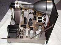
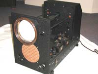
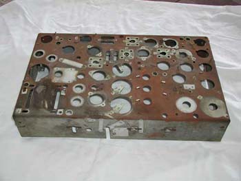
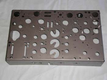
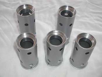
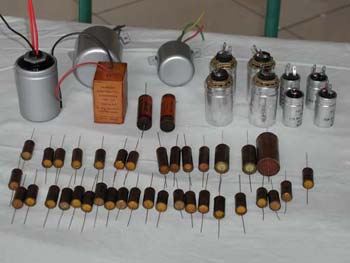
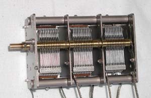
April 2002: I've been cleaning up the yoke assembly. The center cardboard is actually two layers of thin card. I peeled back the internal layer to reveal wooden supports projecting through the outer layer that I left. This increased the internal diameter by about a 1/32" or less and allows the yoke to slip over the neck of some ( but not all!) of my 5FP4 CRTs. Its an interesting yoke for sure. The frame coils have a DC resistance of 5K! Of course the frame stage output drives a sawtooth voltage to produce linear sawtooth current and scan and the load is essentially resistive , however the the line stage has 11 ohm coils and resistance is the enemy there. It relies on the linear build-up of current in an inductor ( in the first part of the inverted exponential curve) when a square wave is "switched" onto it by the output stage, although inevitably there is some resistance in the line stage load and the required voltage needs to be trapezoidal in shape. It will be interesting to see how this works out. I've got a new tube set and sockets coming from the UK and and all the other bits I need like all BA thread screws/nuts are on order. I love fixing up these old sets. May 2002: I found that I could slice off the very end/edge of the caps, with a very sharp new knife just as they rolled around on each end of the cap. If you rotate the cap with one hand and hold knife with other etc. So the total length lost was only about 0.5 to 1mm at each end. Then I could pull out the metal end caps with the pliers by grabbing the wire. Then warming the caps in a convection oven I could slide out the original cap when the wax melted. The new ones were wrapped in fibreglass tape to get a snug fit. Then the ends were poured alternate days with polyester resin( I don't like wax because it melts out at higher temps). The polyester resin sets a smokey color, semi transparent. I also repaired the EHT cap, by putting a protective tape around it, holding in the chuck of a lathe, hand rotating and using a tool to cut a full thickness circumferential V shaped groove in the bakelite base, just inside the alloy lip. The base turned out to be 4 mm thick! I put new caps inside, 0.1uF 3.5KV "Custom" mica caps from Surplus Sales Nebraska. They were the only type of the correct value that I could find that would fit in the can. I re-potted the can with polyester resin( won't be going back in there again!). The polyester also fills the V shaped groove holding the base back on to the capacitor. Other items in the photo are the Square electrolytic in the cardboard box, also potted in with polyester( actually this is the yoke coupling cap) so instead I put in a 10uF Solen Fast 630V non electrolytic from Antique Electronics, so there will never be any problems with that. There are also a couple of other electrolytics that got repaired. Also in the background you can see the repainted line oscillator and output trans. I think the casing of those is a nickel/steel alloy. It was rubbed down, treated with rust convertor, undercoated, rubbed down again with 1200 paper and sprayed with fine silver lacquer. Some tips on polyester resin if you use it: The correct proportion of hardener is said to be 10 to 20 ml per litre, or 1ml per 100ml. It is best to use the smaller amount, especially if you are filling a volume with it. With an object like the can capacitor, or the one in the cardboard box, the surface area to volume ratio is low. As the resin catalyses it is exothermic, so in these size/shape objects it can get quite hot suddenly as the temp builds up, speeding up the process. So for this type of thing I find about 0.8 ml per 100 ml resin is the best as it goes off a bit slower with less heat. June 2002: The electroplating is now complete. The process I have selected for this is "Electroless Nickel" This process electroplates without a DC current, and electroplates down the inside of holes and into corners. It has a beautiful metallic silver look to it and is very suitable for complex shaped small parts, eg the bulb sockets. All of the rust from each component was blasted off (not polished). This leaves a satin surface, completely devoid of any rust particles. You can see just how much rust there was in the pre-restoration photo. As can be seen, this set has a myriad of mechanical parts, each one treated as above, then a coat of protective clear lacquer applied. Nickel's electrons are not particularly sacrificial to steel, but on the other had the nickel maintains an excellent surface, particularly if protected by lacquer or clear enamel. I have been able to re-assemble the speaker. The variable capacitor frame also got electroplated and reassembled after cleaning the corrosion of all its components. It is important that areas of metal work that are protectively clear lacquered, that masking is used in the areas requiring earthing. The yoke was cleaned and some insulation replaced and the yoke re-varnished. The tube shields are restored, by rubbing down with 800 then 1200 grade parer. Treated with rust convertor. Undercoated with automotive primer, rubbed down with 1200 paper, painted with automotive silver. The aluminium tops were polished with 3M marine aluminium polish prior to painting the other parts of the shield. Then the aluminium cleaned with solvent to remove all traces of polish, then the whole shield sprayed with topcoat clear to protect the aluminium and silver paint too. The inner part of the shield was appropriately masked to allow good electrical contact with the ring it mounts on to.
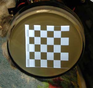
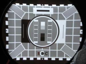
August, 2002: The chain for the radio tuning dial was missing on my set, and I found some similar chain at a hobby shop. Turns. Turns out that I could not stretch the steel chain enough to make it fit the sprockets, so I figured out the exact dimensions of it and am getting a local Jeweler to make it. Turns out these guys only work with precious metals (wouldn't you know it) and it looks like white gold would be better than silver in terms of its physical properties, hardness etc and of course $$. Turned on the set for the first time, a continuous crackle from the speaker, I knew all the tubes and resistors were good. Quickly traced it to the primary of the Audio opt transformer, The DC resistance was 200 ohms too high and when a current passes through it, it generated horrible noise, So I unstacked it and removed the secondary winding and inspected one of the connections to the lead in wires on the primary, it was ok. Then I removed the central cardboard form from the middle of the winding to get at the other connection, it too also ok! So with nothing left to lose I started to unwind the primary from the inside layer. After only 1/3 a layer the wire fell apart and I found a green spot of corrosion. Reconnected it after that fixed up, and problem solved. I rewound the secondary back on with replacement 0.63mm diameter wire, made a new cardboard former for the center, and varnished it up after that, it's still drying. So that should have solved that problem unless there are more green spots waiting to give trouble! Then I can start the alignment I've been doing quite a bit of work on the IF stages, trying to figure out what the manufacturers intended, versus what I can do with it. I've got some great sweep generators and RF sources. The way they configured it is fairly restrictive on bandwidth, only about 1.8 to 2 MHz. That is when I best configure it with a sound frequency of 41.5 MHz and a center vision IF Frequency of 45MHz. On the other hand it is possible to adjust it for a wider bandwidth( as there is plenty of gain), to 2.4MHz bandwidth by re-assigning the vision frequency to about 44,5Mz. One generator I have only puts out a signal with sound and vision 4.5 MHz apart, but with your RF modulators I can tune any value I like. On balance I will probably leave the frequencies as the manufacturers intended, but I know on account of this, the screen image will be "softer". Makes me realise how expectations of a good television image must have changed a lot over the latter 50 years of the last century, and now we take the resolution for granted, like that which make the fine graphics visible on our computer screens. However the American sets of the time appear to have paid more attention to the bandwidth issue. I've had some fun playing around with some different 5FP4's. In general they have quite good images despite only 2.3KV on the anode. The book says they are recommended for 4Kv and above. The advantage they have over a 5AP4 or 5BP4 is that on highlights or over a range of intensities they stay focused! Some I have, the beam centering is a problem and can only just centre the image centred by moving the yoke wrt focus coil. In one case I had to try a small DC current through the frame coils to get a centered image. I've found that by running the line stage at 1/2 our 625 line rate it locks up OK , with good width and linearity, but of course 2 images side by side, but OK for test purposes. I ended tying the anode of the 5FP4 to a lower potential (150 volts) to the screen grid of one of the tubes, V8. With this lowered the CRT was more sensitive to video signal and had better contrast and easier to focus. The IF in this set is really complex and difficult compared to any I have worked on before. It's not just a matter of setting it up for some characteristic with a sweep generator. The sound and vision parts of it interact significantly and there is a fairly narrow set of adjustment compromises which allow a combination of good vision, good sound and lack of interference of sound in the vision and to a lesser degree lack of interference of vision on sound quality. This has all to be satisfactory with at least 25 to 30 volts PP video signal at the tube cathode to get maximal contrast, all with a sensible level of incoming vision and sound carrier. Each time the vision circuit is touched the sound IF needs a small adjustment too. In the end I concluded that the bandpass characteristic the manufacturers intended was not the usual flat top response we are used to. Accepting that, I found that after setting the response as best possible on the sweep generator, that I merely adjusted the tuned circuits for the best looking video signal with a multi-burst test signal from my generator. It is possible on the screen to resolve the 0.8 MHz and 1.8 MHz sinewaves but no more. The 2.8 and 3.8 MHz waves are not visible. Overall though, the signal looks good, with very respectable square edged sync pulses etc. Then when I when back and swept the IF the bandwidth comes out at about 1.4 MHz. If I attempt the broaden the bandwidth the gain in the video drops so you need more RF carrier input for the same contrast, then the vision carrier which comes along with it( from my generator) becomes excessive and interferes with the video. If I use a separate vision carrier, I then have to reduce the sound signal and the S/N ratio in the sound is poorer. So in effect it can all be made to work ok with exact frequencies of 41.5MHz sound and 45MHz vision, if I accept that the video bandwidth is not what I'm used to, and certainly not what a 5FP4 could support. But I suppose the transmissions in those days were pretty "soft" anyway. In my set the height is only just adequate, with all voltages correct, how is yours? I'd bet it would have been better with a choke for the anode load in the frame opt tube rather than that 10K resistor! Have a look at this JPG of the screen image with a checkerboard, 625 line signal. Good contrast and brightness. The image is upside down, as the yoke is rotated around. At the end of line scan the bright bar is the picture getting involved in retrace time and the linearity is poor on what is the left side of the image(if the yoke was in the correct place). When I slow down the line stage to the correct frequency the linearity is fine, and the width better. By loosening the focus coil and adjusting it, I found I could centre the beam on all my CRTs ok. Tuned out that extra accelerating electrode in the 5FP4 is handy to adjust things so the gun probably behaves very similarly to a 3/1. So the 5FP4 is an excellent substitute and really the only option there is at all.
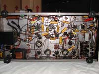
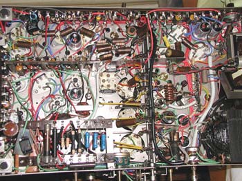
The underside of the chassis |