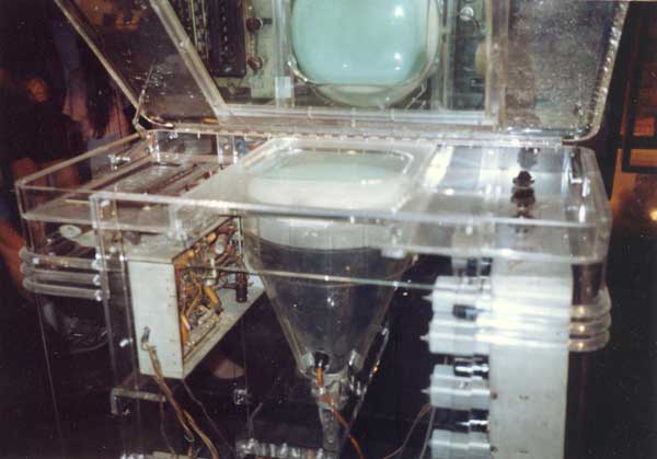
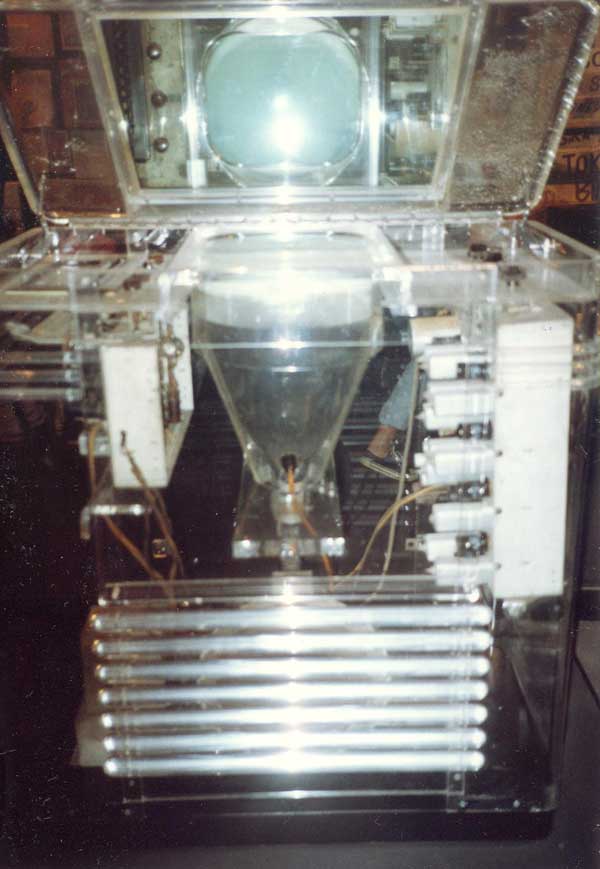
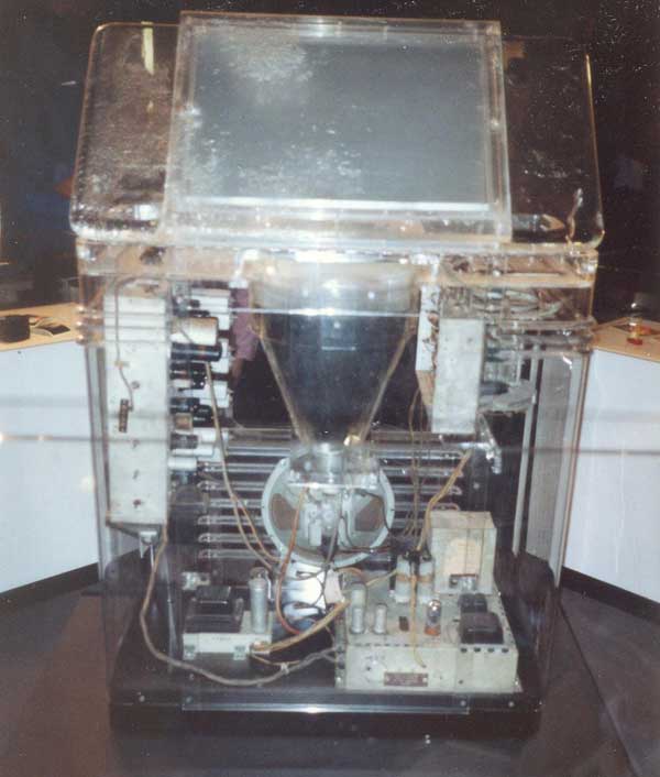
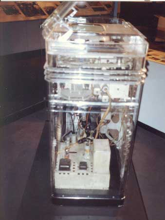
Early Electronic Television Lucite TRK-12 Replica ProjectRecently we were asked by a museum to supervise the construction of a replica of the Lucite TRK-12 that was on display at the 1939 Worlds Fair. The original set is at MZTV in Toronto. We attempted to get permission to photograph and measure it, but were unsuccessful. Fortunately, Pete DePasquale had seen it on display at the Smithsonian in the 80s and had taken good photographs.
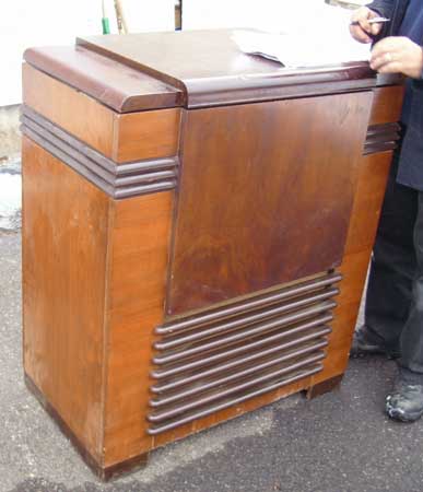
After considerable research, we chose Colorado Plastic Products of Boulder, Colorado to make the replica. Their master fabricator John Butler studied the photos and concluded that he could make the cabinet. Dave Sica generously agreed to loan us his TRK-12 cabinet to use as a model, and we had it shipped to Boulder.
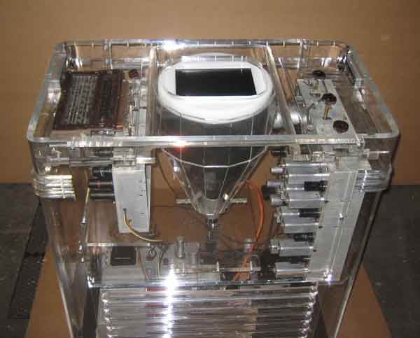
The museum wants to be able to display pictures on the set. Since it wouldn't be practical to operate a 1939 set several hours a day, we decided to use a small LCD display instead. In order to hide the LCD display, we will have a wooden replica of the 12AP4 CRT made, with the display embedded in the top. One issue with the LCD is that the image needs to be reversed on it to display normally through the mirror. This will be done either with a custom Aurora standards converter, or with a PC using custom software. Here are photos of what has been made so far.
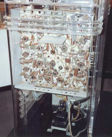
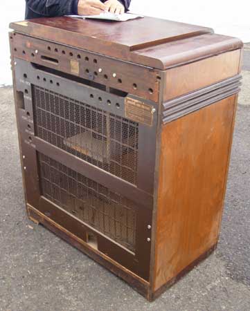
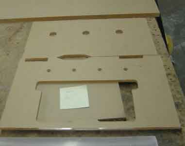
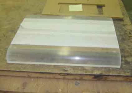
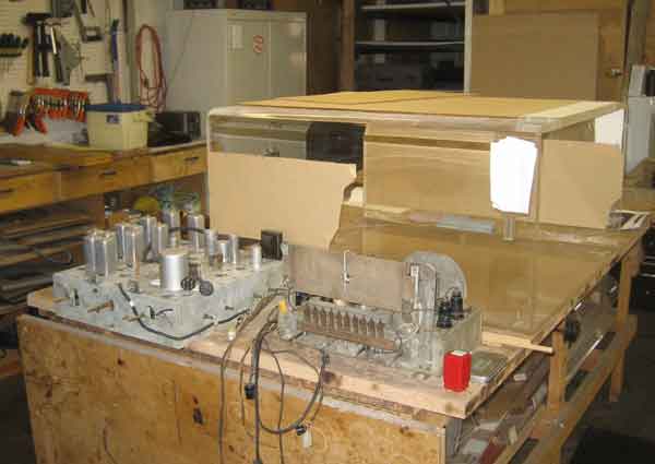
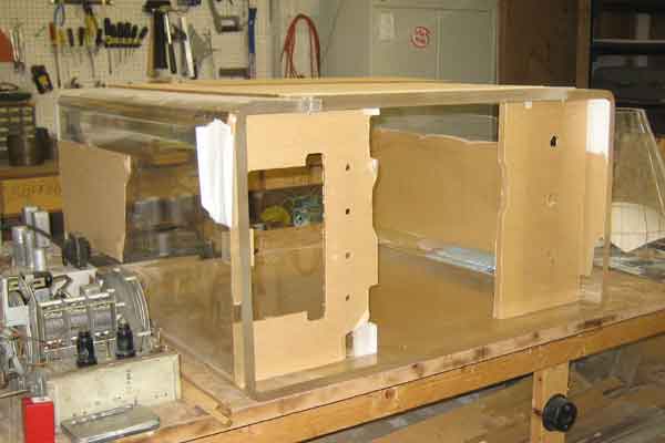
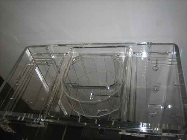
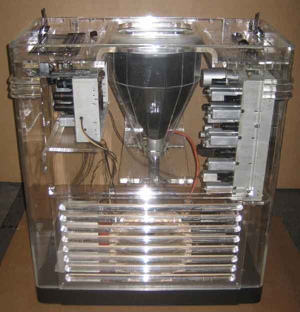
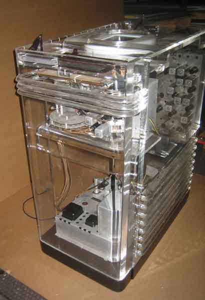
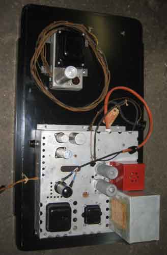
The TV and radio chassis, ready to be installed The cabinet (on its side), with the radio and TV top panels installed. You can also see the cabinet back (on top)
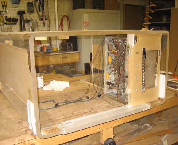
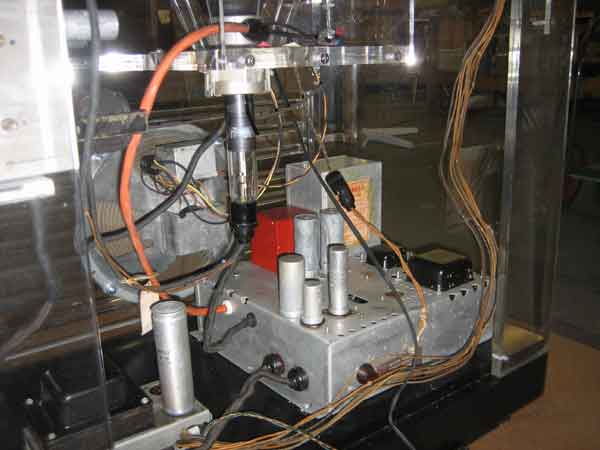
The radio chassis installed
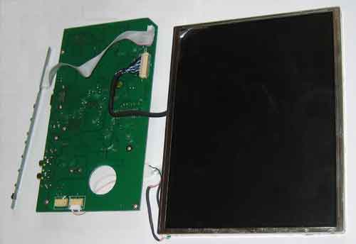
The LCD screen that will be inserted in the top of the wood 12AP4 replica
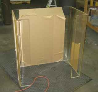
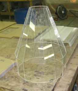
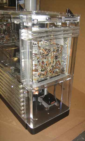
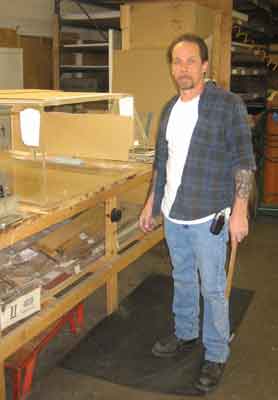
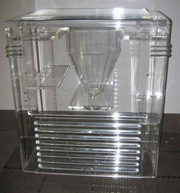
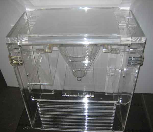
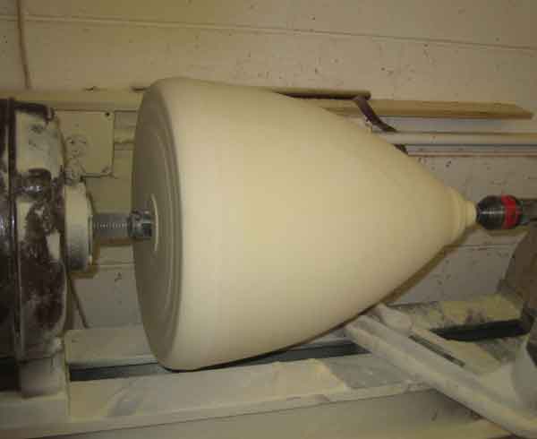
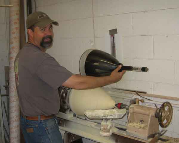
The completed plastic cabinet The replica CRT shell, made of high density foam Casey Balsley, our woodworking expert
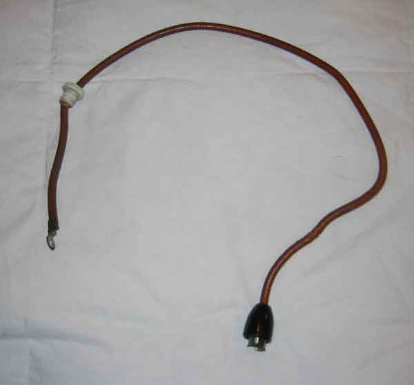
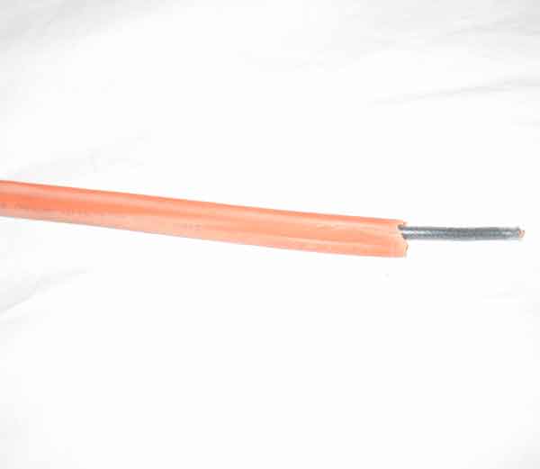
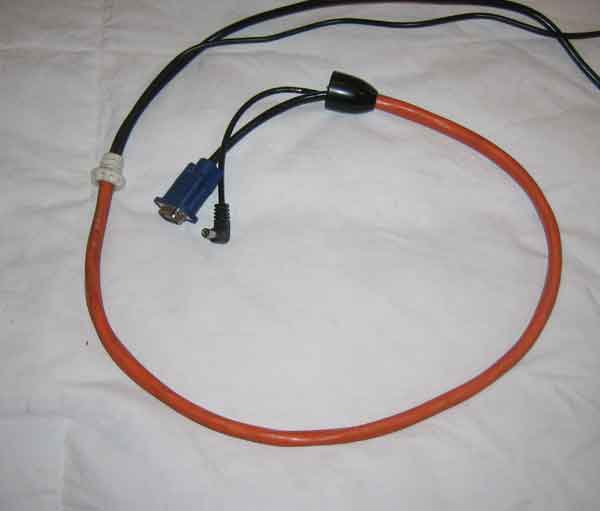
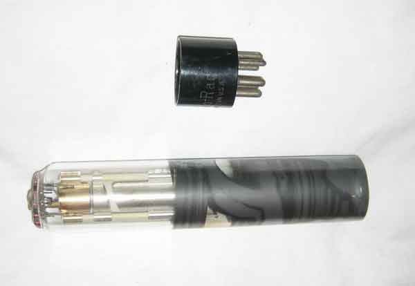
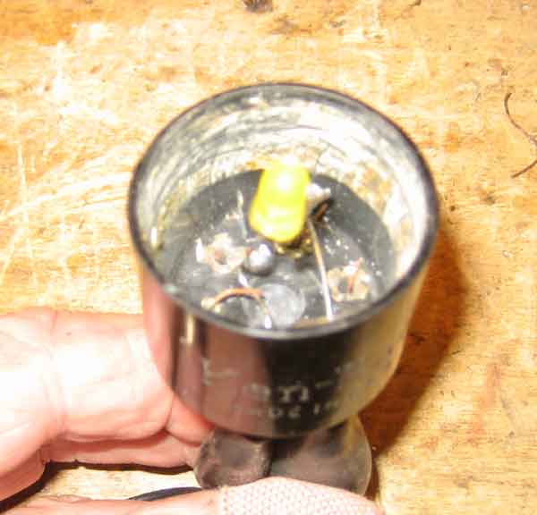
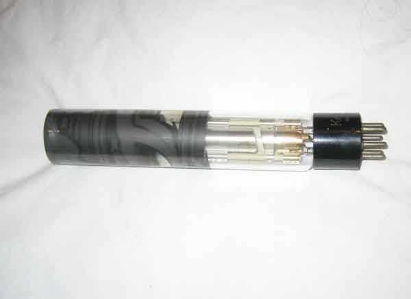
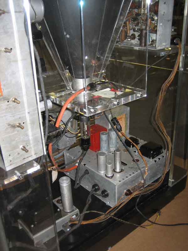
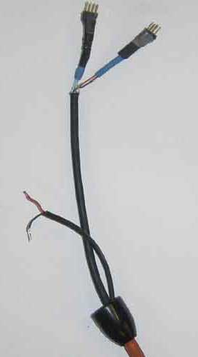
The original high voltage lead to the CRT, which we are replacing with one containing the VGA and power connections for the LCD screen We started with a short piece of 10-3 electrical cable and removed all the wires Then we installed the VGA and power cables inside the sheath and put on the plastic cover that mates with the side of the CRT, and the ceramic insulator that goes in the television power supply chassis. The cables had to be cut to do this, and 3 very small connectors will be installed on the cables. These connectors are small enough to go through the 3/4 inch hole in the television power supply chassis and will allow the other end of the VGA cable to be re-connected. We cut the end off of a 12LP4 CRT and filed down the evacuation nipple A yellow LED was installed in the base and through the evacuation nipple to the electron gun to simulate the glow of a filament Then the base was glued on. The neck assembly will be put inside the deflection yoke, which will hide the joint between the neck and the CRT shell. A LED will also be installed inside the high voltage rectifier cage to simulate the glow of the rectifier tube. A power transformer will be hidden under the TV power supply chassis for the LEDs and for the filament of the 5U4 low voltage rectifier tube. The project is ready to ship. These photos are with the lid removed. The LCD screen is embedded in a white plastic cap over the replica CRT.
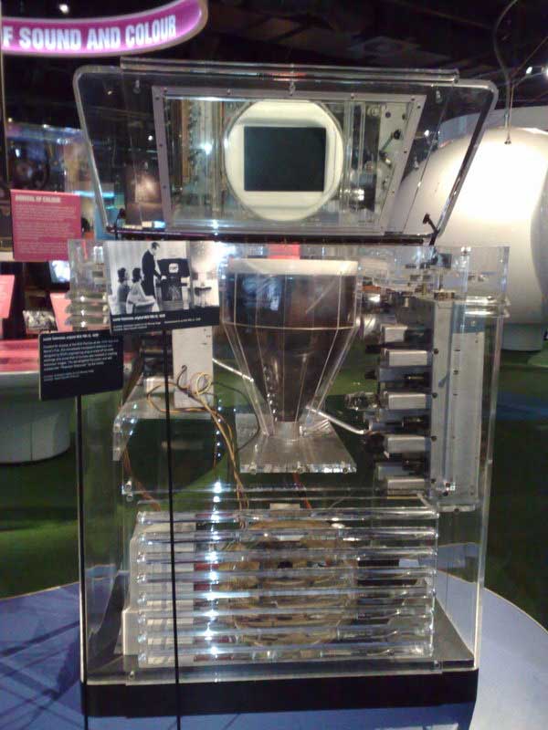
On display at the Australian Centre for the Moving Image in Melbourne |