Postwar Television Panasonic Flat Screen Prototype
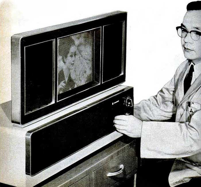
Pictures and text are courtesy of Sean Brady, from the At The Controls Facebook group. New York 1969 - Curious visitors jammed the darkened interior of Panasonic's booth at the March IEEE Show to view TV programs on a screen no thicker than this magazine. The 50-pound experimental set is likely to be a forerunner of flat-screen models that can be hung on walls. The 8.0 x 10.7 - inch electroluminescent screen has 230 vertical and 230 horizontal electrode strips. A phosphor layer between these strips provides 52,900 picture elements. The 0.04 x 0.03-inch size of each element maintains the standard 4:3 picture ratio.
Resolution is fair, but the phosphor has a distinct green hue and contrast and brightness are low. Writing in Electronics, project director Masami Yoshiyama compares the image detail to that obtained from some low-cost video tape recorders. Instead of the odd-even scan pattern used in conventional receivers, both fields are successively displayed on the same horizontal lines. This boosts brightness but cuts resolution.
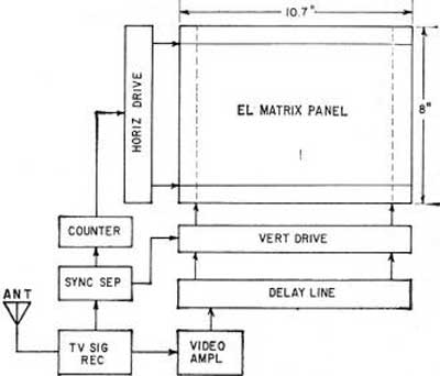
Here is how a single horizontal line of the 230 x 230 matrix is scanned. The horizontal electrode receives a negative selecting pulse, while blanking pulses dim the lines not being scanned. Simultaneously, a sampled video signal for the entire line is applied to all the vertical electrodes. This is accomplished with a 50.6-μsec lumped delay line, which holds the video for the scan line until it can be displayed simultaneously when the horizontal pulse is applied. The brightness of each element is a function of the video pulse amplitude on the vertical strips, varying exponentially, within limits, with the pulse width. The input transistor to each vertical strip serves as a variable resistor, its collector resistance modulated by the sampled video from the delay line. Then, after one line has been scanned, a counter, triggered by the horizontal sync signal, steps the horizontal pulse distributor to the next line. A second horizontal pulse generator simultaneously delivers blanking pulses to all other lines.
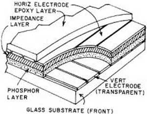
The cutaway drawing of the matrix display panel shows an impedance layer between the horizontal electrodes and the phosphor layer. This reflective coating of barium titanate improves brightness and contrast because of its nonlinear characteristics. The vertical strips are transparent, and the horizontal electrodes are aluminum evaporated.
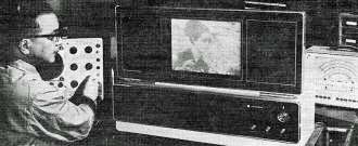
Panasonic plans to test a display panel with an improved phosphor coating shortly. The zinc sulphide compound used now requires dim lighting for comfortable viewing. The prototype model demonstrated at the Show was equipped with provisions for video tape recorders and closed-circuit cameras in addition to VHF reception. With circuit modifications, the display system could be adapted for graphic and alphanumeric readouts. IC's are used in the counter circuits and could simplify the brightness circuits. Some 8,600 components are used in the set, comparable to the number in a desk-top electronic calculator. Power consumption is about 100 watts.
|