Early Television  
Mechanical TV History How it Works Mechanical Sets at the Museum Gallery Database Summary Broadcasting Technical Inforation Restoration Advertising Articles Roger DuPouy's Site Peter Yanczer's Site Gerolf Poetschke's Site Eckhard Etzold's Site
Early Electronic Television History American Sets at the Museum British Sets at the Museum Gallery Database Summary Broadcasting CRTs Accessories Technical Information Restoration Advertising Articles Gerolf Poetschke's Site Eckhard Etzold's Site
Postwar American TV History American Sets at the Museum British/Europen TV History British/Europen Sets at the Museum TV in the Rest of the World Gallery of Unusual Sets Broadcasting CRTs Accessories Technical Information Restoration Advertising Articles Eckhard Etzold's Site
Early Color TV History Sets at the Museum Gallery Database Summary Broadcasting CRTs Accessories Technical Information Restoration Advertising Articles Pete Deksnis's Site Ed Reitan's Color Television History Eckhard Etzold's Site
The Early Television Foundation About the Museum Directions to the Museum Articles about the Museum Support the Museum Join our Email List Our Newsletter - "What's New in Old TVs" Equipment Donations Museum Members and Supporters Members Only Monthly Online Meetings Annual Convention Swapmeets
What's New on the Site Classifieds Parts for Sale Resources North American Radio and TV Museums Search the Site
Contact Us Facebook YouTube Channel

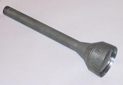
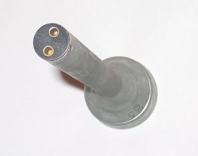
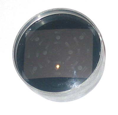
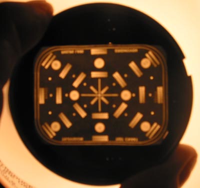
Postwar Television

Television Test Device

This device was sold by Philips around 1950. It is used to align the optical focus of their Protelgram projection units. It is the same size as the 3NP4 CRT. The test device is installed in place of the CRT, and 6 volts AC is applied to the pins on the bottom. The test pattern on the device is projected to the screen, where it can be viewed in a dark room. The image is then focused using the mechanical adjustments on the Protelgram assembly. Then, the test device is removed, the CRT installed, and the electrical focus is adjusted for the sharpest picture. RCA also sold a similar device for its projection sets. Thanks to Chuck Azzalina and Tim Mullen for this information.

Early Television

The test pattern has the words Television Test Chart  Philips Labs Eindhoven. The lettering is reversed when viewed from the lens.

Early Television

The device is about 10 inches long and 2 inches in diameter at the large end. The small end is about 3/4 inches around. It is made of heavy aluminum.

Early Television

The pins on the rear are connected to a bayonette lamp socket inside the flared part. The lamp illuminates a test pattern.

Early Television

This is the front, with a glass lens. The test pattern is visible behind the lens.


Early Television Museum
5396 Franklin St., Hilliard, OH 43026
(614) 771-0510
info@earlytelevision.org