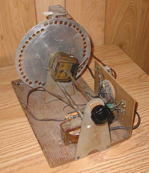
Mechanical Television Western Empire State RestorationThis is a console model lens disk receiver. It originally had two receivers; a AM one for the audio, and a shortwave one (2-3 mHz) for the video. Cabinet. The cabinet is in good condition. The plastic screen is badly deteriorated, and will have to be replaced. Chassis. Here are . The set originally had two chassis. The upper one had a TRF receiver tuning 2-3 mHz and the circuitry to drive the neon crater lamp. The scanning disk assembly was mounted on this chassis. The lower one was a conventional AM receiver connected to an 8 inch speaker, for the audio portion of TV transmission, and also for radio reception. Scanning Disk. This disk is from a Model 41, which was a table model set with a 4 inch screen. We will attempt to adapt it for the Empire State, which has a 6 inch screen. Only the motor, disk, and mounting brackets are original - the wood frame was built in the 80s.
Here is a description of the assembly from a Western engineer, William N. Parker, as told to Peter Yanczer in 1984: At the Western Television Laboratory a search was on for a cheaper synchronous motor. Furthermore, the motor should be able to drive a scanning disc with lenses in place of the tiny holes. The search was prompted by a remark by a West Coast banker after witnessing a television demonstration. He said, "Your picture has definite entertainment value, but the receiver has to be able to be sold for $50.00"! We had been proud of the GE synchronous motor, but the price was obviously much too high. One low-cost synchronous motor investigated was used to operate Tinker Toy models. It had little power and could only drive a small light weight disc. Another synchronous motor was made by Barber Coleman Co. at Rockford Illinois. The parts for this motor could be purchased for less than $1.00 and was quite powerful. However, the synchronous speed of this motor was 1200 rpm--an unusual speed for a two-pole motor operating on 60 cycles. Also, this motor would not operate a disc having appreciable inertia. The solution turned out to be a pair of gears to reduce the speed to the necessary 900 rpm, combined with a slip-clutch arrangement to permit the motor to attain its full speed before the high-inertia lens disc could get up to speed. The slip-clutch included a helical spring to isolate the motor from the high-inertia disc. The spring connected two conical sleeves so as to allow slippage only in the rotational direction which tended to unwind the spring. A small friction disc prevented undesirable torsional oscillations in the spring-disc system and allowed the picture to smoothly pull into synchronism. The scanning disc used with the new motor was aluminum and about 8 inches in diameter. Forty five lenses about I cm. in diameter and having a focal-length of 1 inch were arranged in three interlaced spirals. It was important that the optical centers of the lenses be accurately located to provide a uniform scanning field without dark lines. (or overlapped lines either). Careful hand-sorting enabled the use of relatively inexpensive commercially produced lenses. They were made by the Simpson Instrument and Lens Co. of Chicago. The lenses were seated in counterbored holes in the disc and carefully staked using a drill press The counterbored holes were accurately located using a precision-made jig made on a Swiss boring mill. The cones and other parts were made on a small bench-lathe, (owned personally by Garner). Analysis of time and costs indicated that the $50.00 target could indeed be met. The new scanner was used in two new models of Western Television receivers: a table model and a tall floor version called the "Empire State" model. In both models the picture was viewed on a translucent screen and so could be seen by a number of viewers at once, as compared with the "peep-hole" pictures of previous television sets. The lenses projected the light from a special "Crater" lamp developed by Garner. The tiny but intense light source produced a fairly bright picture on the screen, which was several inches square. Motor designed for 50 Hz operation When we applied power to our motor and checked the speed of the disk, we discovered that it wasn't turning at 900 rpm. So we sent it to Peter Yanczer for repair. He took apart the gear assembly and discovered that the ratio was 2.22222 to 1, and that the motor turned at 2400 rpm. This resulted in a disk speed of 1080 rpm. At first Peter couldn't come up with an explanation, but then he remembered that Los Angeles power was 50 HZ at the time. Western also exported a transmitter and some receivers to Mexico and Canada. Mexico used 50 Hz power, and Canada used 25 and 60 Hz. At 50 Hz the motor would turn at 2000 rpm, resulting in a 900 rpm disk speed with the 2.22222 to 1 gear ratio. Here is a rough translation of a portion of a Mexican TV history web site: 1928 - 1930 PIONEERS: The first experiments in television in Mexico were conducted by engineers Francisco Javier Stavoli and Miguel Fonseca, both professors at the Superior School of Mechanical Engineering and Electrica (ESIME) and of the Industrial Technical Institute. Stavoli was, in addition, the technician in charge of radio station XEFO of Partido Nacional Revolucionario (PNR), installed in 1930, which started broadcasting on January 1, 1931. This is why he was given the financial resources to travel to the United States to acquire a full complement of television equipment, including two mechanical cameras (using Nipkow disks), a transmitter and several receivers, as well as additional equipment to make experimental transmissions 1931 FIRST TRANSMISSION: The equipment brought to Mexico by Stavoli was installed in the building of the ESIME, located on Calle de Allende in downtown Mexico City. The transmitting antenna was placed on the church of San Lorenzo, situated on the corner of Calle de Allende and Belisario Dominguez. After making some field tests, the initial transmission took place, televising the face of Mrs. Amelia Fonseca, the wife of Stavoli, the first image transmitted in Mexico by television. Another quote from William Parker: Western Television equipment was also sold to CKAC in Toronto, Canada and a number of other stations. One set of equipment was shipped to Mexico City, but for some reason was never paid for! Scott Marshall sent this:
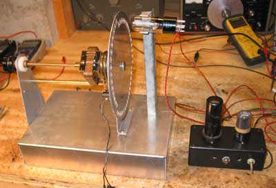
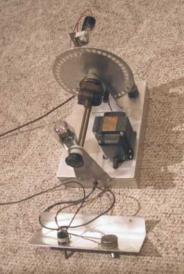
50 Hz power was used in Los Angeles prior to 1936, and it is possible that our motor was designed to work there. Recently we got a 1936 brochure from National Schools in Los Angeles, showing Western equipment. So, our mechanism could have either been made for export to Mexico, or could have been made for use by National Schools. Now we need to find a way to make it work on 60 Hz. There are two major ways we can do this. We can detach the disk from the present motor assembly and build a new one using a modern 900 rpm motor. This would mean that the scanning assembly wouldn't look anything like the original. The other approach is to make a converter to produce 50 Hz locked to the video signal. This could be done in three ways: 1) modification of Darryl Hock's converter to output 50 Hz, 2) build a motor-alternator converter with a 60 Hz motor driving a 50 Hz alternator, or 3) build an electronic converter, perhaps with a 600 Hz phase lock loop locked to the power line, then divided by 12 to produce 50 Hz. The 50 Hz signal would then be amplified to drive the motor. We experimented with operating the motor with 50 Hz using a 100 watt audio amplifier driving the motor. At 55 Hz, the motor would sync, but below that frequency it would not. The motor barely has the power to operate the disk, and at 50 Hz it is less efficient. When the motor and disk assembly was new, it worked on 50 Hz, but with ageing of the bearings and gears, it no longer works. So, we have decided on a different approach. Darryl will modify his scan converter to output a triple interlace 18 fps signal, which will work with the 1080 rpm disk speed with the motor operating on 60 Hz. We have built a chassis to mount the disk assembly on, and built a temporary driver for the neon, using a 6SN7 as amplifier and a 6L6 as the output tube. We have ordered high quality ground glass screen to replace the badly deteriorated one that came with the cabinet. I am visiting the Smithsonian soon to photograph and measure their Western Empire State, in the hope of replicating the scanner and receiver chassis. The scan converter, with 18 fps video locked to the 60 Hz power line, arrived today. When we connected it to the scanner, we got a picture that locked perfectly on the screen. The image is quite dim and difficult to photograph, but relatively sharp. We have installed a new ground glass sheet to replace the badly degraded one that came with the set.
After visiting the Smithsonian and inspecting their Empire State, I've determined that it is not practical to try to build a replica of the scanner chassis. The disk in the Empire is 11 inches in diameter (our disk is 9 inches), the lenses have a different focal length, and the mounting brackets are completely different. Instead, I'll put the drive circuitry on the chassis we have, using a 6L6 as the output tube, 5U4 as rectifier, and a 6SN7 as an amplifier. At some time in the future we may find the original chassis, or be able to build a replica which is more like the original. Here is the replica we have built. The 6L6 and 6SN7 are behind the disk. The controls on the L shaped bracket are on/off/gain (contrast) and neon current (brightness).
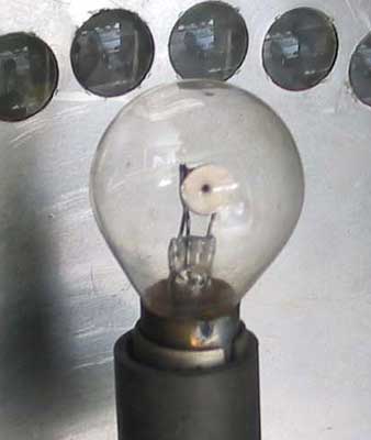
Crater lamps are high intensity neons with a very small spot size. The one used in the Empire State was made by the Garner Co., having a bayonette base and with the aperture on the side of the lamp. These lamps are almost impossible to find, but we finally obtained one. It has a heater element surrounding the crater chamber. Applying about 2 volts AC to this heater assures that the glow occurs within the chamber and not on the attached leads. The original crater lamp was about the size of a large automobile tail light bulb, and has its aperture on the side. We built a replica of the mounting bracket to accommodate the lamp.
We have made a LED replacement for the crater lamp, which allows us to demonstrate the set on a regular basis. |