Peter Yanczer's Pages The Eidophor Television SystemAnother form of innovative television...Note: The information presented here is based on articles or papers by the following; E. Labin, S. M. P. T. E. Journal, April 1950; Earl I. Sponable, S.M.P.T.E. Journal, April 1953; E. Baumann, S. M. P. T. E. Journal, April 1953; Eidophor Training Manual and brochures, supplied by Bernhard Merk, Switzerland. From the earliest days of television, large theater size screen images were a goal for most, if not all of the television pioneers. Some companies in the movie industry such as Twentieth Century Fox were also very interested at the time, because this might provide addition income from their theaters. So they actively promoted and supported the development of suitable systems that might accomplish large screen theater television.The Eidophor system was an example of this and it was in use extensively from the early 50s, until well into the 80s. EIDOPHOR is a Greek word combination meaning "Image Bearer". Invented in 1939, the actual development work began in the early 40s in Zurich, Switzerland, under the direction of Professor Dr. Fritz Fischer. After considering the many problems, he soon came to the conclusion that a very powerful arc light source would be necessary to provide sufficient brightness on a theater size screen. The next problem was how he could efficiently modulate such an intense source of light. Dr. Fischer reviewed all of the light modulators previously used, particularly the Kerr cell, as was used by Dr. Alexanderson in his large screen television work. He found the efficiency of this cell to be much too low for his purposes and so continued his search. Undoubtedly, Dr. Fischer would also have considered the Jeffree cell, used in the Scophony theater systems. Unlike the Kerr cell, which exhibits no memory characteristics whatsoever, the Jeffree cell was able to store as many as 200 to 300 picture elements, providing a significant increase in image brightness on the screen. But even this amount of improvement was not enough to satisfy Dr. Fischer's goal for brightness. Dr. Fischer went on to review some work done by Foucault on the optics of
telescopes and also by Toepler who had described an optical system referred to
as the "Toepler Schlieren" (in German, Schlieren means "streaks" or
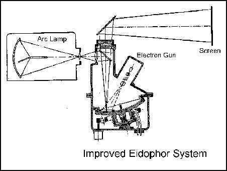
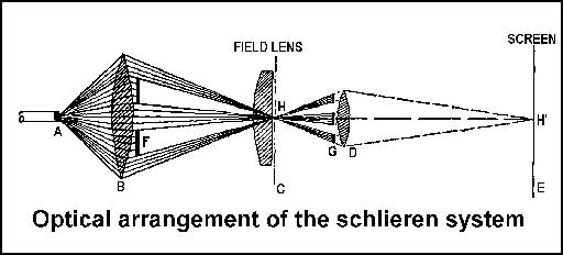
"striae"). His earliest design based on their work was similar to the drawing shown here on the right. This is a light control system based on the phase contrast principle and is a variation of the Schlieren optical arrangement. The arc lamp at A, together with the condenser lens B, produces a uniform illumination of the plane C. A light-modulating or controlling medium is placed in this plane, between the bar-and-slit systems at F and G. A field lens is placed so that it images bar system F upon the opaque bars of system G. The image point at H is located in the image plane C of the objective lens D. This projection lens would therefore image the point H at point H' on the projection screen E. But this cannot happen because the light beams are being completely blocked off by the bars of system G. It should be noted that the incident illumination of every image point at H, is blocked by the strips of the bar system G. However, if a control medium of some sort, is located at the image plane C and could be deformed in a suitable way, diffraction of the light beams would occur. Those diffracted parts of the beams could pass through the slits in system G and on to the projection screen as image forming light. This layer of liquid is called the Eidophor liquid. It takes the place of an emulsion on the usual motion picture film in the film gate, as one would find in the usual projector. If the layer of Eidophor oil is of uniform thickness and homogeneous, light passing through the oil film will not be diffracted anywhere in the image plane C and all of the light passing will be blocked by the bars of G. No light can reach the screen. The next step is to create a form of optical inhomogeneity in the oil film, point by point, that will diffract the light beam past the bars and through the slits of system G. This is done with a beam of electrons from an electron gun, scanning an approximate 3 by 4 inch raster directly on the the oil layer. The electron gun operating at a 15 kilovolt level, deposits electric charges point by point, corresponding to the scanned picture. These charges cause minute wave-shaped corrugations in the surface of the oil layer. Where the oil surface is corrugated as at H1 on the surface C in the drawing, those light rays passing through this point are diffracted and no longer blocked at G, instead passing through the slits and on to the screen. The more the Eidophor surface is distorted, the more intense is the light reaching the screen. A brightness range of 1:300 has been obtained. The drawing to the right shows The Eidophor principle of modulation is for the cathode beam to scan the Eidophor surface, controlled by a video signal in such a way that the resulting deformations are proportional to the instantaneous values of the controlling signal. The actual controlling element is the spot size of the electron beam. The smaller the spot size is, the deeper the deformation of the Eidophor will be, causing more diffraction of light to take place, in turn producing a brighter spot on the screen. The wave-shaped deformations are caused by electrostatic forces in the oil film, due to the electrical charges placed on the Eidophor surface by the scanning electron gun. The wavelength of these deformations is constant, but their height is proportional to the level of the video signal. As the illumination of the image points on the screen are always proportional to the height of the waves at the corresponding point on the Eidophor, the distribution of light over the projection screen corresponds to the video signal and thus to the object being reproduced. The deformation commences at the moment that the electron beam scans a particular point of the image. By a suitable choice of the conductivity and viscosity of the Ediphor oil, the deformation can be preserved for a considerable part of the image scanning period, so that it disappears shortly before the next scan of that point. In the ideal case, the deformation of the oil should remain for the duration of one picture period, but then decay as quickly as possible. In practice, 70% of the ideal is achieved. Since the screen illumination is maintained for this part of the scanning period, a substantial increase in screen brightness occurs due to this light storage effect. After considerable testing, the results were encouraging. A simplified compact prototype model was developed. This is illustrated in the figure below . Notice that it uses only one bar and slit assembly, which is reflective and actually does double duty. Another change in this prototype was the addition of a color wheel, developed especially for the Eidophor system by the Columbia Broadcasting System, using its field sequential color knowledge and techniques. But before this unit could be completed, Dr. Fischer had died and his work was carried on by his associates, directed by Professor Baumann and Dr. Thiemann. Since there is an electron gun in this system, it might be well to point out that the electron gun and the Eidophor oil can only operate in a vacuum. The Eidiphor oil characteristics are subject to change with temperature, so the system includes a means to stabilize the temperature of the spherical mirror and Eidophor oil in contact with it. This is accomplished with a small external refrigeration system.
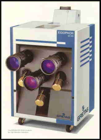
In the main assembly, the projection arc lamp (5) is located at the top left and the vacuum pump and auxiliary services equipment (4) are directly below it. The color wheel (3) is located at the top center. The Eidophor projector (1) is at the lower and center left. The projection light beam hood (2) is at the top right. In later models like the one pictured below, the arc light was abandoned in
favor of hi-intensity Xenon lamps rated at either 3000 or 5000 watts. A color
dot sequential system was also incorporated, replacing the CBS field sequential
method and the purchaser was then given the choice of using the NTSC, PAL, SECAM
or HDTV color systems. The over-all specifications of the more recent models of the Ediophor systems were most impressive. They included these: Screen sizes up to approximately 40 by 50 feet; 80 times brighter than than the best three tube CRT systems; up to 1250 lines horizontal, 120 Hz vertical; Video bandwidth, 50 Mhz; all digital control; white field brightness levels of over 10,000 lumens; projection throws of over 650 feet. What a fantastic system! An engineering marvel, if there ever was one!! Fabulous!!! (Editor's comment) In spite of it though, the Eidophor is becoming obsolete. It looks as if it will undoubtedly be replaced by the LCD and/or the DLP device, manufactured by Texas Instruments, basically an integrated circuit with teeny, tiny little movable mirrors, (pardon the scientific terms).
Peter F. Yanczer |
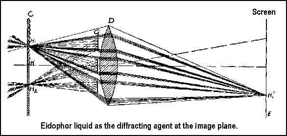 The next drawing here on the
right, shows a control medium, consisting of a liquid oil film of approximately
0.02mm thickness at the image plane C. For the sake of this illustration,
consider this oil film as being supported on a thin, flat glass plate.
The next drawing here on the
right, shows a control medium, consisting of a liquid oil film of approximately
0.02mm thickness at the image plane C. For the sake of this illustration,
consider this oil film as being supported on a thin, flat glass plate.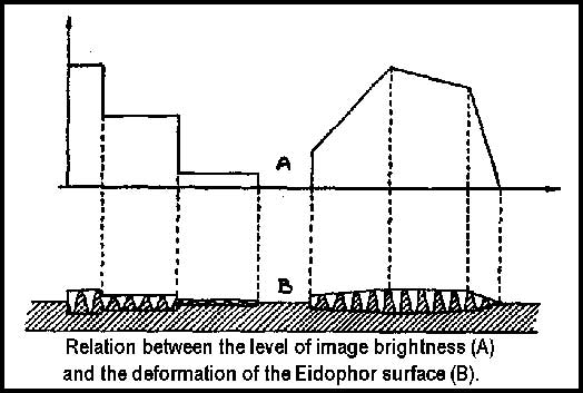 the relationship between the brightness A, along a line of
the image and the amount of the wave-shaped deformation B, in the surface of the
Eidophor liquid. The amount of deformation on the Eidophor surface is
proportional to the desired brightness level for a corresponding point on the
screen.
the relationship between the brightness A, along a line of
the image and the amount of the wave-shaped deformation B, in the surface of the
Eidophor liquid. The amount of deformation on the Eidophor surface is
proportional to the desired brightness level for a corresponding point on the
screen.
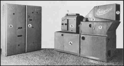 This photo to the left shows a complete system, including
the two upright cabinets (6), containing the low level electronic circuits and
their power supplies.
This photo to the left shows a complete system, including
the two upright cabinets (6), containing the low level electronic circuits and
their power supplies.