
| The Set: Pete Deksnis's Site about the CT-100 Restoring a Vintage Color Television Set |
In January 2007 I measured each primary color of RCA Tricolor 15GP22 serial number IL6057 using a Spyder2PRO operating in the colorimeter mode.
Radiation from each primary-color phosphor was measured by manipulating the screen controls of the CTC-2 chassis driving the CRT. This eliminated nonlinearity contributions by the NTSC system hardware.
This automated plot shows the 1953 NTSC coordinate points for each primary color as a square. Circles describe my colorimeter measurements for each primary color of the 15GP22.
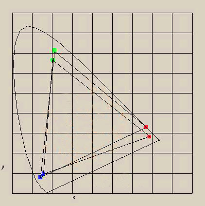
Thanks to Wayne Bretl for this plot of my coordinates.
[BTW: Dexnis is basically Deksnis spelled phonetically, but it's a long story.]
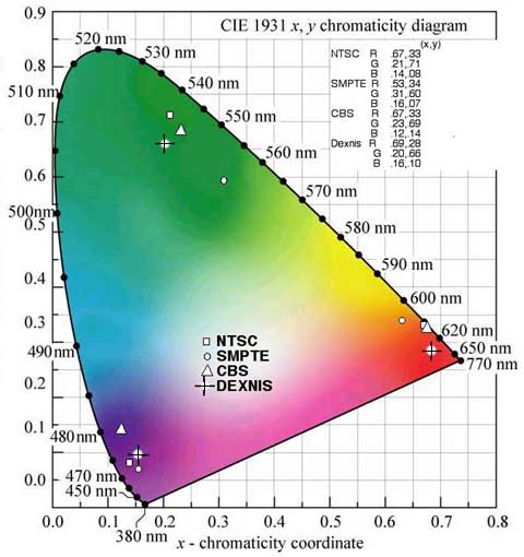
This plot shows primary-color coordinate points for three contrasting standards, including the 1951 CBS Color field-sequential standard, the 1953 NTSC standard, and the modern SMPTE, which matches the '709' high def standard. My measured 15GP22 phosphor data is shown by three plus signs.
If it can be verified that program content has been generated on equipment capable of taking 1953 NTSC color, it may be possible to reproduce wide-gamut images on a calibrated CT-100, or any wideband vintage color set with a 15GP22 CRT.
In an intermediate step, here is a CT-100 screen shot taken January 27, 2007. It shows very interesting red from an NBC video shot in 1968 for "Laugh In." The DVD player is RF-linked to the CT-100 via an S-video link to an S-video VCR, which generates the channel 4 NTSC signal.
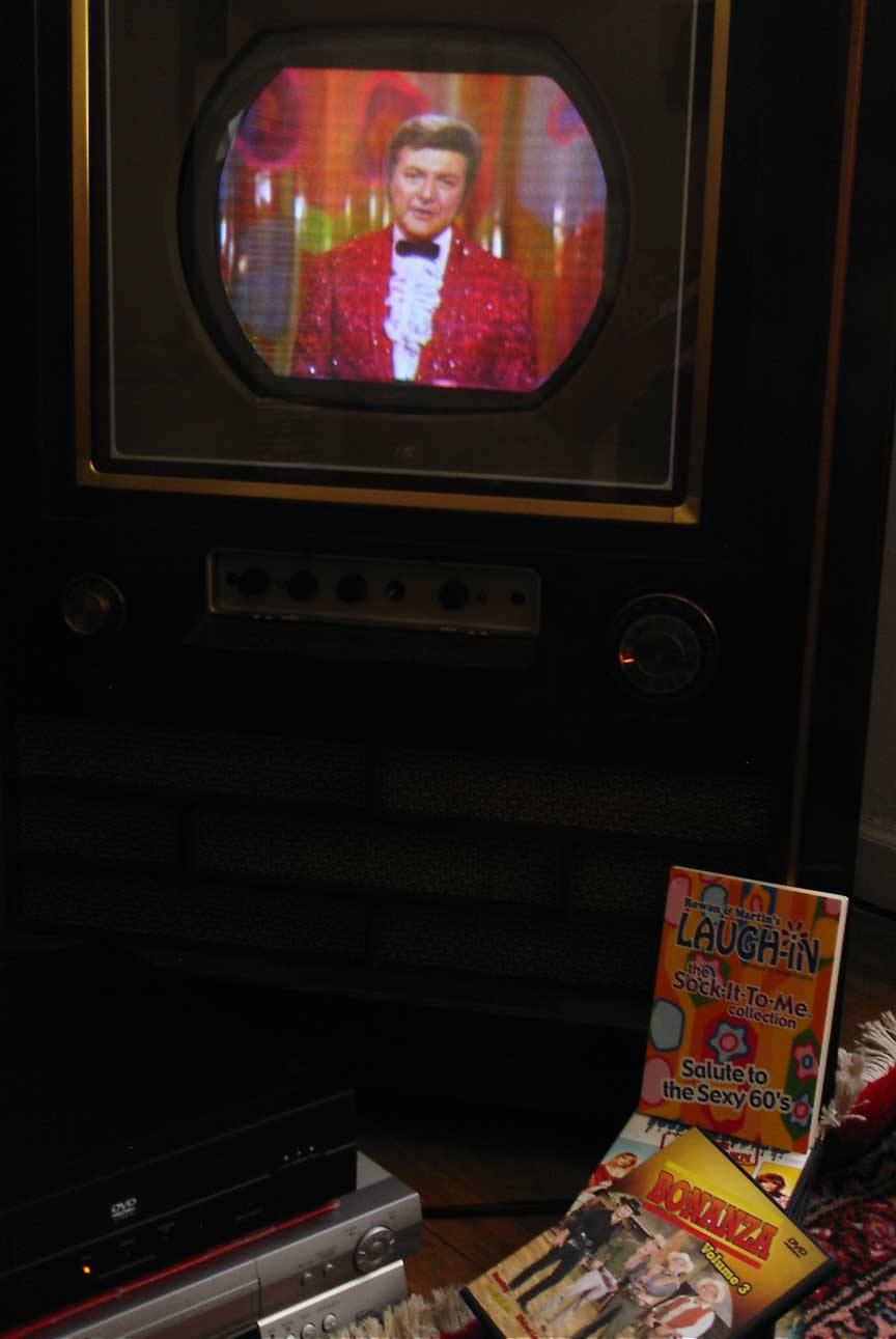
There is a consensus positing that NBC shot 'Laugh In" with the RCA TK-41 color camera. If so, there is a possibility that such vintage programming transferred to DVD is a source of authentic early color broadcast video. There are a number of questions to be raised and satisfied though. Including whether or not the video transfer to DVD used taking curves that support wide-gamut video.
There's also an ongoing investigation with an art director I know, who once taught Photoshop at a local school, to develop a process that generates wide-gamut graphics that can show off calibrated 15GP22 sets.
10 February 2007
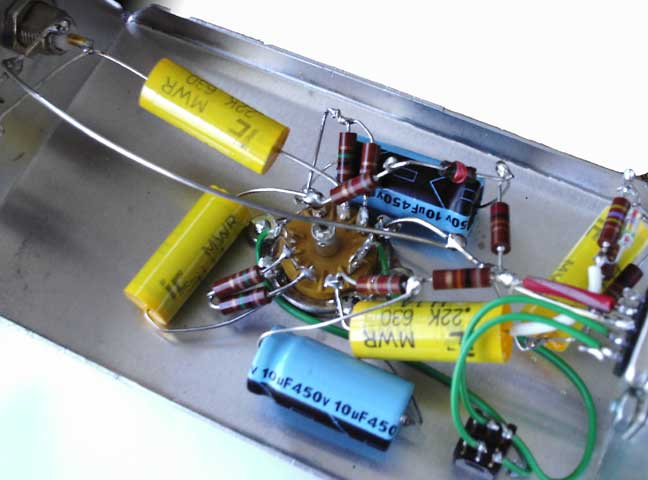
I am building an interface that applies video directly to the control grid of the first video amplifier in a CT-100. This will be used to drive the CT-100 directly with test signals. There are at least two vintage circuits of RCA-design that TV stations used in the latter 1950's to connect CT-100's or 21-CT-55's to a colorplexer. Today, this is essentially the same 'composite' color video signal available from VCR and DVD players at the 'RCA'-type phono jack color-coded yellow.
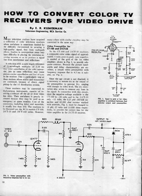
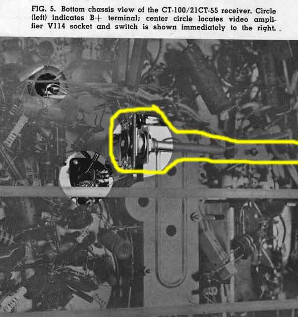
I am using the simpler of the two, shown above, which uses a single 12AT7 on a small aluminum chassis mounted to the high-voltage cage. In an effort to remain historically accurate, the original RCA installation instructions are my guide. Rather than install the switch that was accessible from the front of the set, as shown in the vintage graphic from the article ('Fig. 5' below), I will instead use a relay to switch between TV and Video, with TV as the de-energized state. I am also considering substituting a bias supply circuit to generate -30 volts that is used by the composite interface circuit to bias the CT-100 video amplifier. The -30-volt level developed in the CTC-2 for HO tube bias was used in the original RCA design.
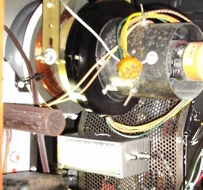
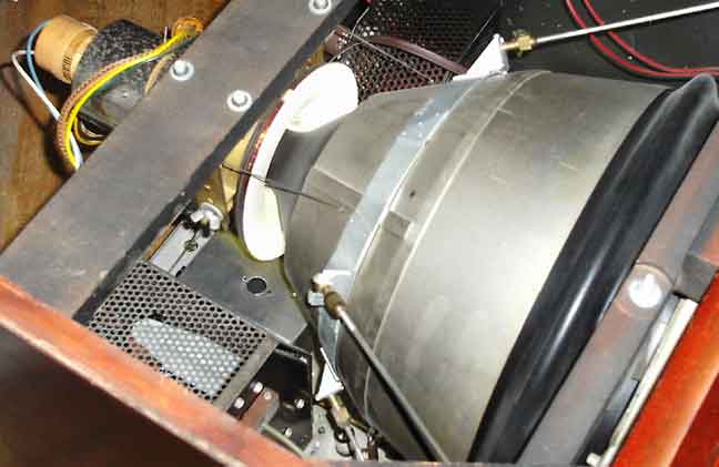
Here next is the under-construction interface chassis being 'fitted' in the available space. As suggested by the Broadcast News article, there is adequate room when the 12AT7 is installed.
28 February 2007
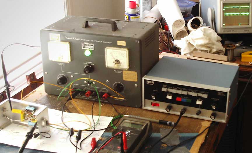
Lsst weekend was spent building and bench-testing the composite video interface for the CT-100.
In my operating CTC-2 chassis, the video detector circuit drives the control grid of the first video amplifier with negative sync tips that are apporximately five volts negative, with the video highlights extending about 2.5 volts above ground, for a 7.5 volt p-p signal swing, well within the capability of the interface to emulate. With a minus thirty-volt bias supply, the sync tips bottom out at minus six volts, and they are held there with changes in video by the 1N34-based dc-restorer circuit.
An easy build, but not a terminal strip in sight; you can't find one at RS anymore.
Below, another shot of the chassis location in a CT-100.
Here next is a close up illustrating the approximate gain of four of the interface, which has demonstrated adequate performance to warrent a trial installation in the CTC-2 chassis this weekend.
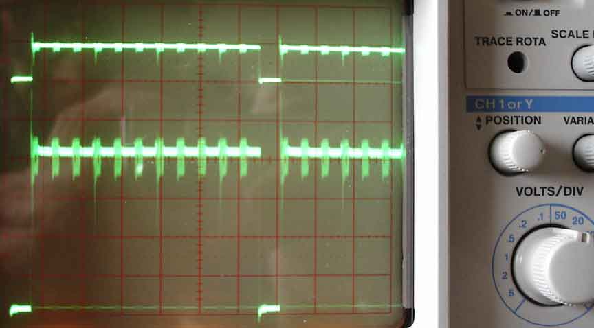
Those three tails dipping down from the color bar traces are the markers that help identify colors.
The adventure continues...
3 June 2007
At the 2007 Early Television Convention in May, this CTC-2 chassis with its composite interface --this 'jeeped' chassis -- was used in a demonstration that reproduced what viewers of color TV actually saw back in the fifties. For a report, click here .
--Pete