|
Television Experimenters.com
Light Sources
First a bit of history... plus a suggestion!.. Read through this testament once or a few times before you cut up any wood or whatever. You need to know how it all works and how the parts play together and fit together. Use your ingenuity to make it an even better fit for your particular application. PY.
One of the things unique about the mirror screw is that it requires a different light source, as compared to all the other types of scanners. This was bought out in the original patent papers by Mr.Gardner, in his description of the operation of the mirror screw. The light from the lamp also needs to be modulated before it illuminates the mirror screw. At the time there were not many ways known of how to modulate a light of any sort, especially in a low cost manner. In a later patent #1892142, related to his mirror screw, he showed a means of modulating a gas flame electrically. However, in this day and age, we might be inclined ask for something more simple and less dangerous.
In the early years, two approaches were used. The most simple being an incandescent lamp, quite long for its diameter, with an extremely thin filament wire from one end to the other. This was about the time that John Logie Baird had successfully demonstrated an array of over 2000 filament type lamps. The signal modulation was applied directly to the filament circuit along with a DC bias. For 30 line operation, this proved satisfactory. A more common approach was to use a Kin-O-Lamp, the same as those used with other mechanical scanners.
TeKaDe used this method in some of their earlier receivers. The lamp was in a socket, with a hood that had a rectangular opening for the light to pass through. This whole assembly could be rotated about 90 degrees by means of a small handle attached to the socket. A short distance from the lamp, there was a pair of large cylindrical lenses mounted face to face. This type of lens set has the property of converting a large area light source to a line of light.
|
|
On a Kino--lamp, there are two plates in the internal structure. Only one is active and actually emits light. In this application, only the light from the edge of the active plate is directed towards the lenses and onto the mirror screw. By rotating the lamp a few degrees, some of the light from the surface of the active plate can begin to get through, adding to the light from the edge. This results in more light through the lenses and on to the mirror screw, which results in a brighter picture. However, since the light image at the lamp has effectively widened (edge light+surface light), the line of light now falling on the mirror screw will provide lesser resolution than before.
There were also attempts to use a form of sodium lamp, which offered high brightness and good response, but the yellowish color was not acceptable nor was the constant RF field bias that was required for the lamp to work.
Another approach was to use a powerful incandescent lamp along with a Kerr Cell. This was a proven method and TeKaDe improved it further by developing a solid state version of the Kerr Cell.
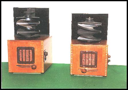
I built my first mirror screw receivers around 1986. Both are 120 line screws, the taller one being made of stainless steel and the other aluminum. Both shown here on the right. The electronics in both is the same, a simple audio amplifier driving the speaker. Other than that, there is just a synchronous motor.
While the construction of these two units was going on, I tried to find something on the design of the light sources. I found almost nothing. So I spent some time on an optical bench, which in my case was a 2" by 4" about 3 feet long. I had some lenses, ground glass material, various LEDs, all mounted on small pedestals, that I could attach to the 2 by 4 and run some tests.
|
Based on the tests made, I found that since I would be dealing with a line of light, cylindrical lenses would be most useful. I had on hand, various lengths and sizes of clear styrene round and half-round material, left over from some previous work and it fit right in with what I was doing. My original design used only the round sections of styrene and was for the most part satisfactory. The first four light sources were set up like the drawing here on the right, but without lens #2. The
way it works is that the LED puts out a cone of light and is placed at such a distance from the styrene rod, that
this cone just expands to where it covers the width of the rod. The rod acting as a lens, has a focal distance
of about 1/4". |
|
At that point approximately, are the two thin metal pieces cut from the beer can, spaced the same as thickness of one of the mirrors in the mirror screw. The distance between the gap and the rod can changed by loosening the screws in both ends of the styrene rod. The correct adjustment is indicated when the light passing through the gap is at its brightest with the light intensity even over its entire length. Sometimes it may help to move the LED array sideways a small amount and finally, one needs to try rotating the rod as much as 180 degrees either way. Once an optimum position is established, the two end screws can be tighten just enough to keep the rod in place.
|
|
About 2 years after doing this work, I noticed that the light was falling was on much, much more than just the
mirror screw. I found the solution to be adding a half round section of This resulted in a brightness boost of three to four times. Reversing the half round sometimes showed an
improvement too. You should try it both ways. |
So, here is how you might start out. You will be mounting 5mm LEDs in a straight line, the number depending on the height of the stack of mirrors in the mirror screw. Multiply that by 1.25 to get the total length. The LEDs mounted take up about 4 to the inch. For the screws that I've built, I recommend as a minimum the following number of LEDs: large 60-line=28 LEDs, large 32-line=22 LEDs, smaller 60-line and 32-line=18 LEDs. Connect small 32 line mirror screw, you will have 9 pairs of LEDs connected in parallel, each pair with its own resistor. I use PCBs that I make for myself. An alternate way is to use Vector Board material. The color of the LEDs is up to you. I prefer white and the brighter the better. Wiring to the amplifier, if it is less that a foot, whatever you have will do. For longer runs, use miniature coax.
|
|
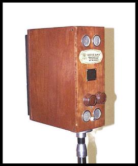
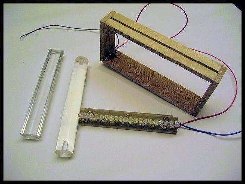
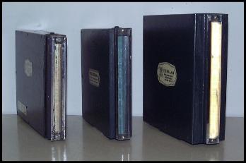
You will need a case or box that will support all of the all these parts in a proper manner. On some light sources, I have included the video amplifier and its power supply. This of course means that the box needed to be larger. The first one I built, shown here on the left, had everything in it. It measures 10" tall, 4" wide at the back and 1.5" at the front. However, I don't recommend it, even though I have done it twice now. There is plenty more room in the main cabinet, where the motor and mirror screw are located.
Whatever the space requirement for the LEDs are, add an inch for the mounting and that will equal the inside height of the box. I suggest that 1/4" plywood is suitable construction material, making the outside dimension of the box a 1/2" more. As for the width of the box, I'll suggest a 1.25" dimension.
|
In order to determine the depth of the box, (front to back) let's find out what is in the box first. Imagine the box with the plywood top
removed.. Looking down into the box, here is what we will find. In order to determine the depth of the might not have expected. One is
round box, (front to back) let's find out what is and the other is about half round, both in the box first. Try to imagine the box is referred to as "Styrene".That is only half finished and we will see what is inside by the word. The whole word is Polystyrene. It is not intended to be used in the manner that I use it here, but it works, it works well and it is cheap! |
|
In both cases it acts as a lens. Acrylics can also be used. The round section is 5/8" diameter. Its purpose is to
capture the light from the LEDs and condense it into a narrow beam as it passes through the box. On the outer
surface of the box, at the opening, there are two thin metal plates, placed long edge to long edge, but not
touching. These are to be separated by the same amount as the thickness of one of the mirrors in the mirror
screw. For the thin metal plates, if you have nothing else, take an aluminum soda can and with scissors cut and
discard the ends of the can. One more cut and you will have a piece measuring about 4" by 8". This material is
about .005" thick. If you have a paper cutter, cut two pieces of the aluminum about 3/8" wide, for the full length
of the material. The reason for the paper cutter is that you will need to have a really strait edge after you cut it,
so that when you put the two together and set the gap (remember, one mirror thickness!) the gap will be the
same throughout its length. Put them aside for now.
Setting the position of the LEDs.
Using a battery or power supply of any sort, light one of the LEDs that you intend to use and cause the light from
it to fall on a clean white flat surface. Moving the LED nearer or farther from the surface will cause the circle of
light to change in diameter. When the majority of light falls into a 1/2" circle, measure the distance from your LED
to the flat surface. That will be the distance from the LED to the center of the 5/8" diameter rod. Record the
number.
. |
|
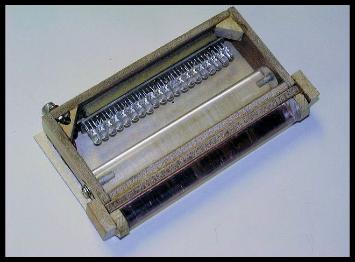
Now for the box, or should I have said "Enclosure"?
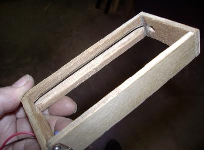
I have left the picture large so that you might better see what you will need to do. This box is about 1.25" wide. The back, top and bottom are the same width and the joints are cemented with a good grade of carpenters glue. You might have noticed that there is a slot in the front of the box. That is where the light comes out. The slot is about 3/16 of an inch wide. On that surface you will be cementing those two thin strips that were cut from the soda can. That comes a bit later.
The picture also shows the styrene rod that is threaded 8X32 by 3/8" deep on both ends. It fits snug in the box and the holes in the rod line up with two 3/8" holes in the top and bottom of the box |
It might be necessary to locate the Styrene closer to the metal strips that form the gap. That is the reason for carving out the backside at the
inside corners. You could accomplish this by just thinner lumber at the front. I did that some later builds. On my latest, I'm using 1/16" aircraft
plywood in that location and the side covers, not shown here. One of the covers can be glued in place, the other held on with six to eight small wood screws, so as to be removable.
Barely visible, is the input connector, type RCA. |
|
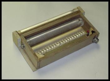
This picture on the right brings out an important detail about the front of the box. It might be necessary to locate the Styrene closer to the metal strips that form the gap. That is the reason for carving out the backside. You could accomplish this by just thinner lumber at the front. I did that some later builds. On my latest, I'm using 1/16" aircraft plywood in that location and the side covers, not shown here. One is glued in place, the other held on with small wood screws, so as to be removable. Barely visible, is a connector, type RCA.
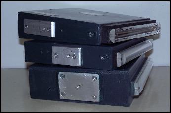
Here below is the light source, photographed from the front and rear. The half round appears lighted, no! it's just the camera flash. Here below on the right is something you need to include on every unit. A means of mounting it.. Many times a camera tripod works out well. The three light sources on the lower right each have a small aluminum plate, about 1/4" thick with 1/4 X 20 threaded hole that will fit most tripods. These plates are held to the bottom surface of the light with typically two to four screws. Notice that of the half round on the top
light source is reversed compared to the half round on the second. That is the way it works out sometimes. The lenses all need to be adjusted with all of the LEDs operating with a low level DC excitation, for evenness in lighting, top to bottom and for the greatest light output falling on the screw.
|
|
|
When adjustments are completed, the operating location of the source depends on the number image lines. With 120 lines, I locate the light source about four the six feet from the mirror screw. On 60 lines, I set it about three to four feet and on 30 an 32 lines I set it from one to two feet. You will find that the distance of the light source to the mirror screw has an effect on the apparent image size and these are the settings I have found most useful.
|
 |
 |
Peter Yanczer

All rights reserved.
|
