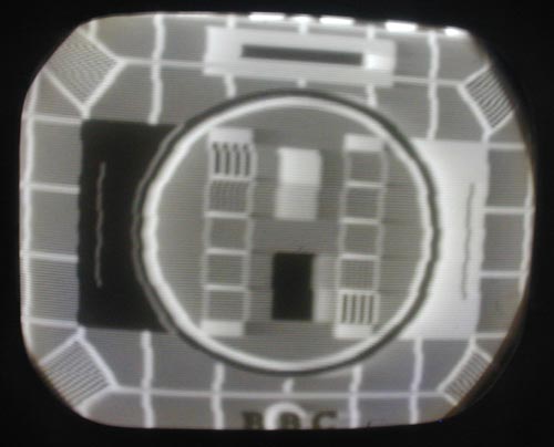
Early Electronic Television HMV 1800The Cabinet. (pictures) The cabinet is intact, but the finish is in poor condition. We will take it to Old World Furniture Refinishing to have new lacquer applied. The CRT is a 9 inch magnetic deflection, magnetic focus tube with an unusual neck. After restoring the chassis I connected the tube and got a very dim raster. I will try the tube again after I receive the new high voltage (EHT) transformer, which will supply more voltage to the tube than the temporary transformer I used. Here is technical information. The Chassis. (pictures) There is only one chassis in the set. It is in relatively good condition, with a small amount of rust, only on the rear panel. There appear to be many postwar components that have been added to the set. We don't have a schematic for this set, but ones for other similar sets will help. The high voltage (EHT) capacitor also had to be rebuilt. The chassis has been significantly modified, especially in the sweep circuits. Several of the original electrolytic capacitors have been replaced by modern ones. I received a schematic from David Boynes of a similar set. After tracing the circuit of our set I discovered that it is actually the same as the schematic, but at some point a very sloppy serviceman installed replacement parts in a very haphazard way, bypassing the terminal strips and connecting the parts together in mid air. I hare rebuilt the paper capacitors in the vertical (frame) sweep section, and have restored the components to their proper places. The horizontal (line) sweep sections and the sync separator and amplifier have been rebuilt. The sync circuits had been modified to be similar to the postwar design. I returned it to the early electronic circuit. The sweep circuits now appear to function properly. The electrolytics have been rebuilt, and the modern ones replaced with old style cans. Though the set now looks more authentic than it did, some of the cans are not the proper ones. The high voltage (EHT) transformer started smoking, and will have to be rewound or replaced. Ed Dinning in England is building me a replica, which will be about the same size. After replacing bad RF amplifier and oscillator/mixer (frequency changer) tubes (valves) and finding a couple more wiring mistakes by the previous repair person, I got a good video signal at the output of the video amplifier. I discovered another bad electrolytic capacitor that will have to be rebuilt. There was no audio output, using an audio test signal into the output tube (valve). After checking and rechecking every component, I discovered that the plate had been tied to the screen grid by a wire that was not easily visible. I removed it and now the audio amplifier stages work. The audio from a RF signal source is distorted, however. The remaining items to be completed before putting the set aside until the transformer arrives are to find the audio distortion and to test the sync separator circuits. The problem with audio distortion turned out to be in my modulator. After repairing it, the sound is fine. I connected a temporary high voltage (EHT) power supply, providing about 2500 volts rather than the 3500 the original supply put out. The raster was extremely dim. When I get the replacement transformer I will try the CRT again. The replacement high voltage (EHT) transformer arrived. It is somewhat larger than the original, but, since it is located under the chassis, it will not be visible. After connecting the transformer, I had no raster. I traced the problem to an off value resistor in the video output stage, which was applying too high a voltage to the CRT cathode, forcing the tube into cutoff even with the brightness control fully up. After replacing the resistor I had a dim raster. I noticed that the CRT filament appeared to be very dim, so I measured the voltage and found that it was 2 volts instead of the specified 4 volts. I traced the problem to a poor solder connection on a small inductor that was in series with the filament. I then had a bright image on the screen, but no vertical (frame) deflection. The problem was that the can style electrolytic capacitor I had used as the coupling capacitor in the vertical (frame) output had the negative lead internally tied to the can, resulting in a short to the chassis. Replacing the capacitor solved that problem. The set is now displaying a bright, sharp picture (this photo was taken at 1/4 second exposure. This set has a slight wobble in the picture caused by operating it with a 60 Hz supply instead of the 50 Hz it was designed for. As a result the photo is blurred.)
|