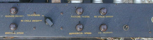
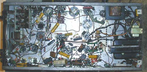
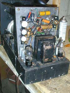
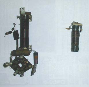
Early Electronic Television Meissner 10-1153 RestorationThe Cabinet: This set has no cabinet. The Chassis: The chassis is in good condition, with no rust. It has been washed with a mild detergent. This set is very basic, with no RF amplifier and only two stages of video IF. It would have worked very poorly outside of a major city. Here is technical information. We have a schematic diagram for this set. However, this set is significantly different from the diagram we have. 1. There is an extra switch on the front panel (not a factory modification). This switch controls the high voltage (EHT) power supply. 2. There is an extra switch on the side of the chassis and an extra hole on the front panel (not a factory modification). This switch inserts a trimmer capacitor across the fine tuning control. Apparently the set had so much local oscillator drift that the fine tuning control had insufficient range. The bandpass of the AM detector is very broad, so drift would not have been a problem. When the set was modified for FM sound, tuning would have been more critical. So this trimmer was probably added with the FM modification. This explanation isn't correct. The original fine tuning control has a range of several mHz. In working with the tuner I noticed that not all frequencies could be tuned in with the 4 switch positions, and there are no adjustments on the oscillator coils. Maybe the switch and trimmer were added to tune the set to a channel that the 4 position switch didn't allow. 3. There is a switch, phono jack, and two pots added to the side of the chassis (apparently a factory modification). They apparently allow the power line to be used as a source of vertical (frame) sync instead of the normal sync pulses. It also allows some sort of external vertical (frame) oscillator to be used in place of the internal one. 4. A FM sound detector has been added. A limiter stage (6AC7) and ratio detector (6H6) have been added under the chassis. We have traced the extra circuitry. The "60 Cycle Sweep" and "FM Phasing" controls connect to the 6.3 v filament line, and vary the amplitude and phase of the 60 Hz signal. When the "Television/60 Cycle Sweep" switch is in the 60 Cycle Sweep position, this signal is fed to the vertical (frame) oscillator in place of the TV sync signal. Meissner used the wrong time constant in the vertical (frame) integrator circuit, which would have made the vertical (frame) sync unstable. The sync generators at TV stations were locked to the power line at that time, so it is my speculation that this modification allowed the user to lock the vertical (frame) oscillator to the power line to get more stable sync. The switch shown on the right side of the above photo, and the phone jack just visible at the edge of the picture bypass the TV sync signal out of the jack, probably to an external sync separator and oscillator, then back into the vertical (frame) output amplifier. We will now rebuild the paper capacitors (see the procedure for this). Each electrolytic capacitor will be tested for leakage and capacity. If bad, new electrolytics will be installed inside the old ones. The set has two power transformers. The one that supplies the high voltage (EHT) has been replaced with one that doesn't have a 6.3 volt winding for the CRT. A separate transformer was apparently added for that, but it is missing. For now I will use a modern transformer until I can locate an old one. After installing that transformer and replacing a number of rotted wires, I fired up the high voltage supply, and it worked properly. I then applied reduced voltage to the other transformer, which supplies 300 volts for the B+ rectifier and filament voltage for the other tubes (valves). After a few minutes three of the electrolytic capacitors overheated, so I rebuilt them. Two more electrolytic capacitors overheated, and have been rebuilt. All of the capacitors in the time base circuits are mica. I found one bad, and rebuilt it. The wrong value resistors were in the focus circuit. After changing them I have a raster. There is hum in the horizontal (line) sweep, coming from the high voltage (EHT) supply. I will next rebuild the bypass capacitors on the centering controls, which could cause the hum. Several parts are bad. The inductor in the plate of the video amplifier is open, and I will attempt to rewind it. A resistor in the power supply, which is bolted to the chassis, has developed a short to the chassis. There are several places where parts have been cut out. All of the capacitors in the sweep, video and CRT circuits have been rebuilt. A resistor in the horizontal (line) output amplifier was the wrong value, resulting in poor linearity. It looks like the set was built that way, and probably never functioned properly. The set now displays a good raster. I decided to remove the FM sound modification and put the set back to its original design. I am now troubleshooting the video IF amplifier, mixer and local oscillator. There is something intermittent in the oscillator, probably a dirty contact in the switch. The problem with the oscillator is not mechanical. For some reason it quits periodically. Removing the 6J5 and reinserting it makes it work again. RCA has a separate 7 volt winding on the power transformer of their early electronic sets for this tube (valve). Apparently it is marginal at VHF frequencies. I aligned the IF stages according to the assembly manual for a bandwidth of 10 to 12.75 mHz. Aligning this set was among the easiest I have done, and the results are excellent. Meissner was a maker of inductors, and used their design expertise to make coils that resulted in excellent IF performance. Meissner had fantastic pre war coil technology with their "ferrocart" ferro magnetic cores, and not relying on the primitive brass slug technique like in the HMV sets (information courtesy of Hugo Holden). After finding a couple more bad resistors in the vertical (frame) output section, the set now displays a good but dim picture. The 5BP4 CRT is weak. The sound also works well now. The tuner problem was a 35 pf coupling capacitor. It tested good, but replacing it made the tuner work properly. The restoration is now complete. The rear safety cover of the set is missing. I will attempt to find someone to make a replica. After operating for a couple of hours the set developed two faults. First, arcing was creating lines in the picture and noise in the audio. The arcing was coming from the high voltage (EHT) transformer. I discovered that reversing the high voltage winding leads caused the arcing to stop. Apparently the windings were breaking down near one end, and by placing that end at a low potential the transformer didn't break down and arc. A second problem was that the sensitivity was erratic. Sometimes there was adequate contrast and volume, but at other times the sound and picture were very weak. Since the fault affected both sound and picture it had to be in the oscillator or mixer. My spectrum analyzer indicated that the local oscillator strength was not changing, so the mixer was at fault. The problem turned out to be an intermittent resistor to the screen grid. This is a very unusual type of failure, and was apparently caused by corrosion around the lead entering one end of the resistor. The final problem involves the 5BP4 CRT. I have several, and only three of them have relatively bright pictures. They are in the RCA TT-5, TRK-5 and GE HM-171. I have several made by DuMont, and they are all dim and have a yellowish appearance. I also have two made by other manufacturers that are bright, but have a vertical band and distorted sweep. The final tube is the one I've put in this set. It is not very bright, but can be viewed in a darkened room. Under the chassis after restoration. Note the modern filament transformer, which will eventually be replaced with one from the period.
|