Ed Reitan's Color Television History CTC-4 Color Receivers (1955-56)
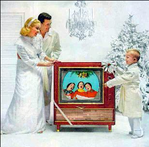
A White Christmas with the CTC-4 CTC-4 Chassis Model Series
RCA released the Service Data for the Models 21-CT-661U (CTC-4) and 21-CT-662U (CTC-4A), "1955 No. T5", on May 4, 1955. A second edition was released on December 9, 1955. A significant number of changes to all circuits were made in a "late production" design and documented in Service Data Supplement "1957 No. T10", issued September 4, 1957. This described the 21CT660U & 661U (CTC-4), the 21CT662U (CTC-4A) and the 21CT663U & 664U (CTC-4B). RCA also published a Television Service Clinic booklet, "Technical Features of the RCA Victor Model 21CT66U Color Television Receiver" in 1955. A comprehensive 91-page Television Service Clinic booklet, "Servicing Color Television Receivers", covered details of both the early and late production CTC-4 chasses in 1956. "The CTC-4 series also had its picture displayed on the screen of a 21-inch tricolor kinescope, the 21AXP22, with an area of approximately 255 square inches. The CTC-4 was the first "simplified" chassis with a greatly reduced tube count of 25. A UHF-VHF tuner (KRK-37) was provided for all sets. Customer tuning was unique - when the inner knob was rotated from VHF channels 2-13 to a UHF position, the VHF Fine-tuning ring became a two-speed UHF tuning ring. Rotation of this ring would initially fine tune nearby UHF channels, while further rotation would go into high speed rotation for distant UHF channel selection. I have been told that Hallicrafters patented the concept, and traded its use in exchange for RCA providing chasses for the Hallicrafters color receiver. The RCA CTC-4 chassis was also used in cabinets sold by Magnavox and DuMont. The CTC-4 had three stages of I.F. Amplification, two stages of Video and used Narrow-Band R-Y and G-Y Color Demodulation. The chassis was the first to use printed circuits for the video I.F. strip and the sound I.F strip. A 6CB5 was used for Horizontal Output, a 3B2 for HV Rectification, and a 6BK4 Shunt Regulator. A 1X2B was used as the Focus Rectifier. Additional features include: a removable top panel to facilitate servicing and adjustment. The CTC-4 chassis was vertically mounted on the right side of the cabinet. A small sub-chassis was mounted behind the tuner for 12 convergence adjustments and five color screen and background adjustments. Single, dual and triple loudspeakers were provided for sound reproduction in different models. The set consumed 375 watts. The CTC-4 photo is from its Service Clinic manual. Don Kent did the PhotoShop colorization of this image.
V1.01 04-26-1999 Copyright 1999, Ed Reitan
|