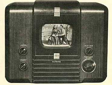
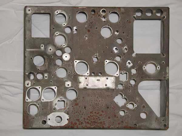
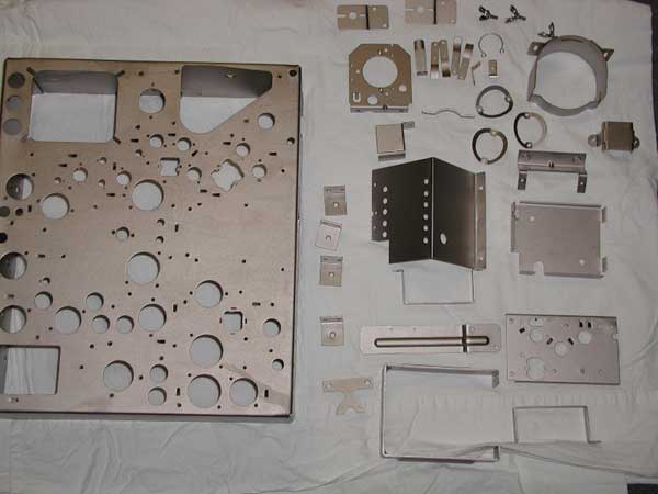
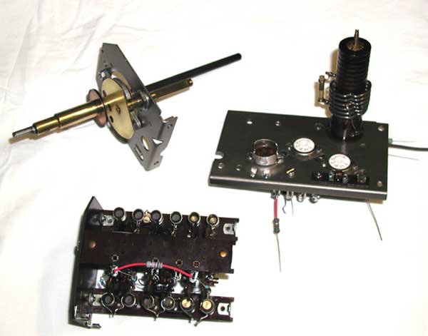
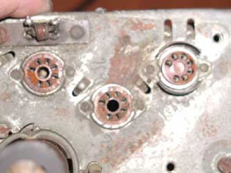
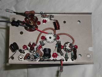
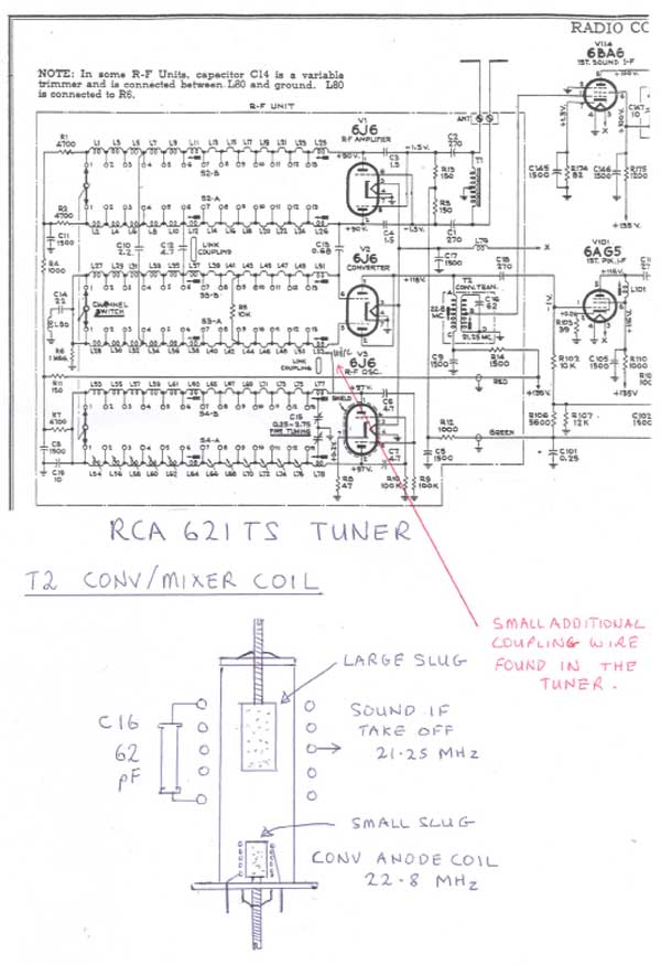
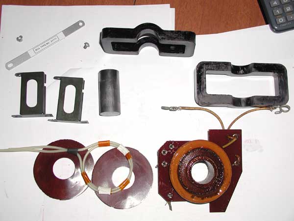
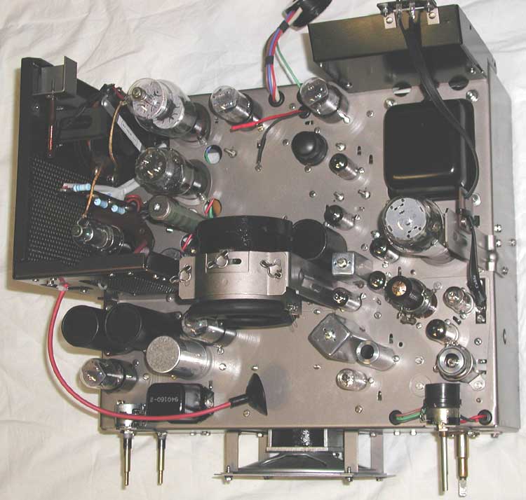
Postwar Television Hugo Holden's RCA 621 Restoration Hugo Holden has undertaken the restoration of another set, stripping all components from the chassis and rebuilding it like new. He purchased the RCA 621TS in the United States, and had it shipped to Australia. Hugo's earlier restorations included an Andrea KT-E-5, a Meissner 10-1153, and a HMV 904. Here is a narrative describing his progress: I'm in the process of restoring the 621. All the metal parts were stripped of the original cadmium, aluminium oxide blasted to remove every last microscopic rust crystal, and treated with the process of "Electroless Nickel" doesn't use an electric field. This plates into corners, and hole edges with an even thickness, in this case 20 Microns. It gives a great metallic look. Most electroplaters won't do cadmium now(Toxic concerns) and the fact is that the Electroless system is much better for complex shaped formed objects. However your electroplater must have a good knowledge of electrochemistry and be very patient to get this sort of result. Here are before and after photos of the chassis and other metal parts: As you can see I'm also rebuilding the tuner and also I've had to replace the power transformer with one of the same sized stack (and similar windings) the Hammond 300BX, still keep the original transformer covers so it looks the same. I have attached some before and after photos of the tuner restoration, and also a diagram of the "Spectacular" converter or mixer coil. At first thought this outrageously large coil looked like is was just for show, but a closer look reveals that it is a very clever piece of engineering. Have a look at the diagram below.
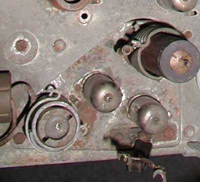
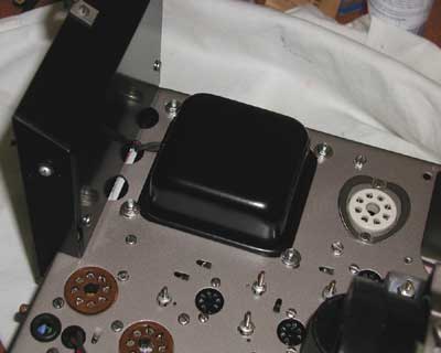
The tuner in this set is "space age" sophisticated for 1946. Features include a neutralised push-pull RF amp with neutralisation based on a 6J6, a 6J6 Kalitron oscillator and the spectacular mixer coil driven by the combined anode signals from another 6J6. Also the use of both ferromagnetic materials and brass slugs is advanced. The idea behind the mixer coil is to create a very high Q loosely coupled selective sound take-off. The large sound IF coil is spaced away from the former to avoid it being tuned by distributed capacity, it is largely tuned by the "high Q" 62pF dog-bone ceramic cap. The mixer anode coil for the video is broad tuning and loaded by the 10 K resistor and the plate resistance of the 6J6 mixer tube. With regards to the tuner restoration, I have replaced most of the bypass / coupling caps with silver mica ones, except the local oscillator feedback caps, these were replaced with 500V 4.7pF mil spec dogbone ceramic caps with the same tempco which match the originals, the same goes for the 1.5pF neutralisation caps on the 6J6 RF amp. Also used mostly metal film resistors. helps keep the noise down a little. The tube sockets are nos, including a the original push on shield type for the L/O. I got a nos push on shield, identical to the rusted up original from Angela Instruments. The rivets and the original screws have been replaced with 4-40 and 6-32 stainless steel screws (avoids future rusting). These can be obtained from PSME (Precision Scale Model Engineering). PSME is in Milford, MA, email psme@psmescale.com and the fellow who runs it, Lawrence Milo is very helpful. Although there are locking washers, never hurts to apply varnish to the threads, in this case my wife's Chanel No 5 nail varnish. I'll send you a complete photo later. It is probably fair to say that a tuner restoration itself is about 1/3 the work of the main chassis and other componentry. As you can see from the before photos, the tuner body had unacceptable rust and bad sockets, so I gave it the "treatment".
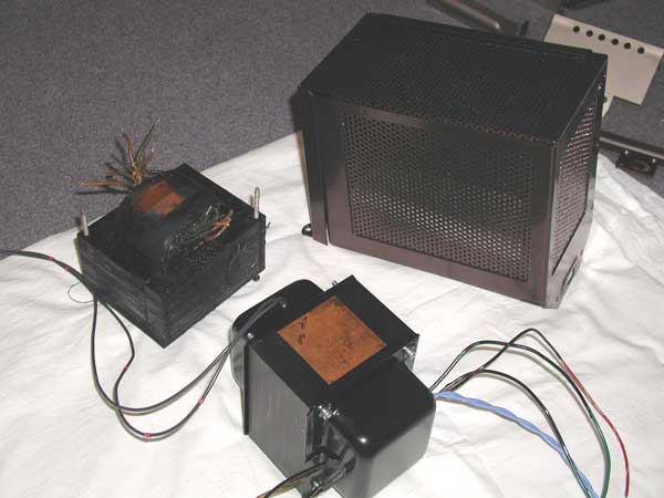
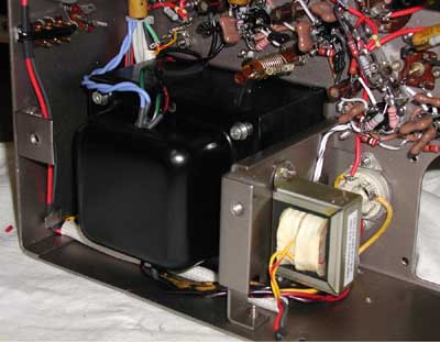
Shown in the photo is the original 621 power transformer, I took the copper flux band and restored covers off it and added them to the Hammond 300BX transformer, and discarded the Hammond covers which are quite different. The two transformers have very close to the same geometry stack, with the holes placed a little differently. The original brackets were blasted free of rust and black powder coated and the finish looks very similar to the original and is corrosion and scratch resistant. The two wires for the 120V configured primary windings have to exit via an additional hole in the top bracket. The original 621 transformer is not a safe proposition to run here in Australia with our 50Hz supply frequency. The transformer has very aged and cracked insulation and runs an excessive magnetisation current on 50Hz. For example, off load, the RMS current on 115 to 120V, 50Hz is 1.5amps(compared to 47mA for the Hammond configured for 120V which is designed for 50/60Hz). In general old 60Hz American transformers run hot here on 50Hz, also there is significant stray magnetic fields generated. So the Hammond transformer solves the problem. The windings on the Hammond are close to exact: Two 1.2 A 5V, parallel to 2,4A to run the 5V4G Damper diode, One 5V 3A for the 5U4G one 6 V 6A for the main heaters, and one 800Vct for the HT.There is only one winding "missing", a small 6.3V one for the CRT heater, but I'm adding a small auxiliary transformer for that, there is a convenient place to mount it, and only one hole needs to be drilled to fit it. (on Hammonds website, their data sheet says the 300BX has only one 5v at 1.2A winding when in fact it has two of these). In the background is the restored EHT (high voltage) cage. This had the rust and oxide blasted off. I could not get any electroplating done which would resemble the brassy bronze color that it once had, so to get a good look, and protect it, I had it powder coated with metallic bronze, it looks very good now. I've also attached a picture of the EHT (flyback) transformer that was disassembled to clean the rust from the core and varnish the windings for improved protection. The core has a darkish blue colour now due to the organic rust converter. I had to replace the 2 turn heater winding for the 1B3 as the original had degraded insulation, I found some identical geometry wire inside the red sheath of some modern 25Kv anode wire. All of the large Allen Bradley resistors in the focus chain were open circuit! So I've replaced them with 10Kv rated Philips focus grade resistors. Also the doorknob cap has been replaced with a 1000pF 15 Kv (same physical size as the original 500pF) and this help to allow for the CRT if it has no external aquadag. I'm not 100% sure if the original doorknob cap is ok, it only reads 375pF and I've read reports of them failing in the 621. The work on the set continues. The underside of the chassis is now re-wired, all new resistors, wiring and tube sockets. The resistors are now all 2 watt metal film, but yet the same size as the original 1/4 or 1/2 watt types. 500V Silver mica caps were used to replace the original moulded micas, and the wax paper caps re-built with poly's with twice the voltage rating. The cardboard shells had all the wax cleaned off and were varnished with marine grade varnish, so they look excellent but the surface is not tacky to touch and won't adhere to so much dust as is the case with wax. The octal sockets were replaced with American mil spec brown phenolic sockets with wrap around pins and stainless steel saddles. The 7 pin sockets replaced with American phenolic sockets from AES. Antique Electronic Supply (USA) have supplied all the new capacitors, including the micas, electros and poly's and also a good number of NOS tubes for the set as well as the 300BX power transformer and new tag strips. They always send me excellent tubes and parts at competitive prices I find. The adjustable IF coils had very rusty spring mounting clips, they were all replaced with new ones as they are a common standard part on many NOS old stock coils. The originals were soldered to the chassis on the top, presumably to prevent capacitive effects varying and altering the IF tuning. I this case I simply soldered them to the nearest earth lugs under the chassis with a short link wire to avoid soldering to the chassis on the top surface. All of the potentiometers, except one, were restorable to a good standard, the on/off vol pot got replaced. The new wiring is medical grade silicone rubber covered hook-up wire which looks exactly like old fashioned covered rubber wire, but is extremely heat resistant and this insulation never melts back near the solder joints (even if the iron is on 480 degrees C). The wire is pleasant to handle and flexible, but stays where its put on the whole. It is about 2.5mm outside diameter and has 16 strands. Once you have used superior wire like this its very hard to go back to PVC covered wire or anything else, including Teflon. This silicone rubber wire is available from RS components. I stuck to the color scheme on the wiring diagram where possible. Fabric covered wire is available, though I suspect it would meet the same fate as the original wire over the next 60 years. The silicone rubber wire will outlast it I'm sure. Ideally I want the restoration to look about the same 50 years later, the chassis, as well as having the 20 micron thick nickel, also has a good coat of protective lacquer. This also avoids corrosion and finger marks. In general, during a restoration, its best to build all the lightweight components back in first and add the heavier items later. That way the chassis is easier to handle. I've wound a small 1:1.17 ratio isolating transformer which gives 6.3 to 6.3V rms at 0.6 amps load to provide the heater supply to the CRT from the power transformer's 6.3V winding. At turn on from cold, the heavy loading of all of the TV's low resistance cold heaters results in a good slow rise in initial heater currents due to the limited current delivering ability of the power transformer, and in that sense the larger tubes protect the smaller ones at turn on. In series heater chains resistors or thermistors are needed as the internal resistance of the mains is very low and the initial surge current in the cold heater chain is very high. The smaller tubes warm up first and more voltage is developed across their heaters without current limiting. However it is interesting to note that the same problem will occur "within" in any indirectly heated tube, if you connect the heater pins across a power supply of very low internal resistance. The part of the heater, close to it's internal connections, warms up first as there is less thermal inertia there than the part in contact with the cathode, and you will get an initial bright flash from that area of the heater at turn on. In fact you can get this effect if you unplug nearly all of the tubes in your TV, except for a small one, at turn on you'll also get a bright flash, as the large power transformer is, under these circumstances, able to maintain the 6.3 volts across the single tube's pins nearly immediately. All that needs to be done now is to add the tuner, rebuild the EHT area, add the yoke and the power resistor box and the 5u4 and it's socket and power transformer, and also fit the black cardboard insulating covers over the electrolytic cans, fit the CRT socket which has been cleaned up with new flying leads, then fit a NOS set of tubes and test and align the set. Hmm, then there's the cabinet!
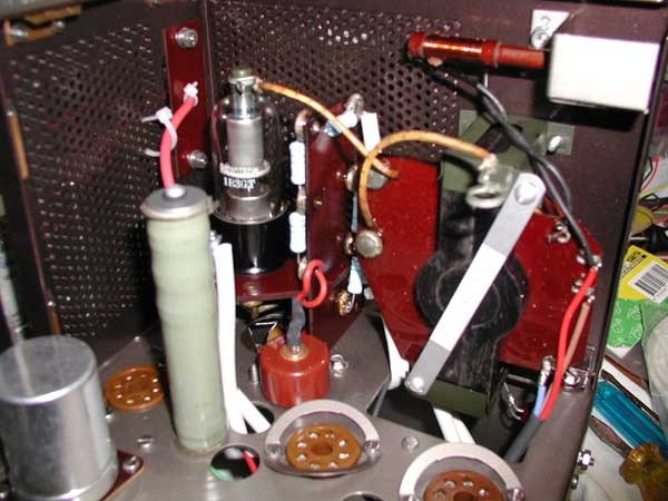
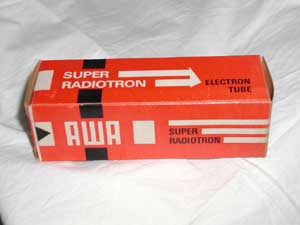
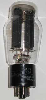
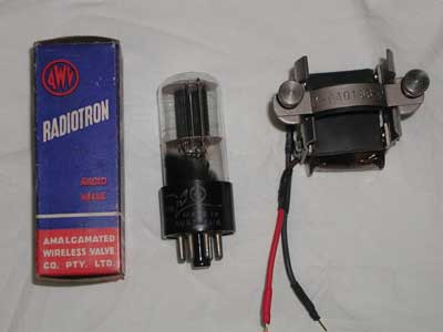
As the 621TS restoration progresses I'm awe inspired by the futuristic technology that it employs in 1946. The 621 is a special set, America's first post war "mass production" set, however made in limited numbers. This set represents the culmination of pre-war television technology and concepts which were distilled by 1938 and 1939, before WW2 disrupted proceedings and diverted the attention of Electronic Engineers to the war effort. The photo shows the inside of the EHT (high voltage) cage with the 6BG6 line (horizontal) output tube and 5V4 damper tube and the 6SN7 Horizontal osc and discharge tube not present to improve the view. At a glance it is obvious how the technology was progressing, and in fact, was in this case, setting the standard for all monochrome TVs to follow. The first person to suggest the use of a "damper" diode in magnetic deflection scanning, in 1936, was Alan Dower Blumlein, the "inventor" of stereo audio. He patented "binaural" audio recording in 1931. Of course people thought he was "nuts" at the time, because this would require twice the hardware for both recording and reproduction and it didn't seem to be an economical prospect. Alan was killed in a plane crash in 1942 while testing radar for the war effort. This loss was described by Winston Churchill as a national tragedy. Following this, damper diode function was well examined by RCA laboratories presumably during wartime and in the immediate two years thereafter . RCA produced a series of review articles and in "Magnetic Deflection Circuits for Cathode-Ray Tubes" Otto. H.Schade Volume V 1947-1948 Pg 105, RCA Labs, reference is made to Blumlein's original 1936 patent, and damper diode technology is thoroughly explained. I've written an article describing the development of the damper diode. Over the following years it became obvious that magnetic line scanning systems really needed to be "Energy control and management systems". The energy required to deflect the beam to the right, stored as the potential energy of the magnetic field in the yoke and line output transformer, could be recovered after flyback, and returned to the power supply, by the damper diode, and the left side of the scan generated by damper diode current. Therefore the line scan energy required is just enough to overcome the losses, now much less in the absence of energy wasting resistive damping. This idea was a huge leap forward in efficient scanning, and over the years, damper diodes became synonymous with "efficiency diode", or "booster diode" (due to the availability of boosted B+ voltage). No doubt this also paved the way for the concepts which have resulted in modern switchmode power supplies. Also in the photo the new EHT (high voltage) bleeder and focus chain resistors (10KV rated Philips resistors) can be seen attached to the "framework" which mounts the 1B3 EHT (high voltage) rectifier. This framework is composed of clever interlocking pairs phenolic sheets, which all lock together when the 1B3 socket is inserted. Now for something "Australian" to add to the project. The 1B3 shown in the EHT (high voltage) cage photo, and the box it came in (the other photo), is Australian made, by Amalgamated Wireless Australia (AWA) probably some time in the 1960's or early 1970's. AWA had a massive tube plant that made versions of most of the common RCA tube types, for both television and radio. These tubes were every bit as good as their American counterparts. AWA also made radios and appliances for Australia going back to 1913 when it was founded in Sydney. Some of their wonderful Bakelite 1930's era radios, like the AWA Fisk Radiolette, that look like an Empire State building, attract high prices from American collectors. This tube plant does now not exist. It was a terrible loss to Australia. The company made its last products in the late 1970's and ultimately after being acquired by a gambling and betting agency (Casino's and Tab) evolved into an information and communications technology company. The AWA brand is still licensed out however. In respect to this great past tube maker, I will also fit an Australian made 5U4G. Don't worry, all the other tubes will be American!
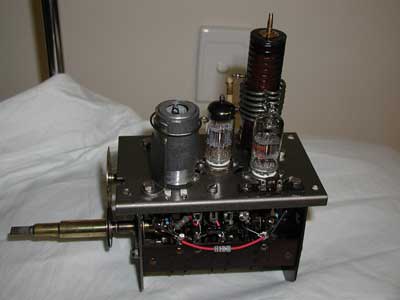
Progress continues, the tuner is finished now. It has a very impressive tube shield arrangement with a push on metal shield, with spring flanges, which contact the bulb of the 6J6 local osc tube to the shield. Around that is a thick lead shield which is attached by a spring clip to a stabilising arm to the tuner top plate. Clearly very effective mechanical and electrical shielding which would also reduce microphonic effects probably. The photos show the restored tuner fitted with NOS tubes ready to install back in the set, and the other photo is of the top of the tuner the way it looked prior to restoration mounted in the chassis. Its good to see the tuner looking like it must have when it was new, 60 years ago.
I've installed the 300BX power transformer and I've taken a couple of photos that might be of interest to others restoring the 621. The small added transformer (to supply the picture tube heater) started out life as a Hammond P-T166L6 115V/ 6.3V CT. I took all the wire off the bobbin and re-wound it, primary 93 turns of 0.63mm dia wire and secondary 110 turns same wire, eg a ratio of 1:1.18 so it yields 6.3V at 0.6A from the main 6.3V supply. The original Hammond 6.3 volt winding was rated at 2A and had a total of 60 turns. Its better to run a higher turns per volt within limits of the copper losses and regulation being acceptable, to reduce the core's magnetization current and stray magnetic fields in a TV application. As can be seen in the photo, the black powder coat on the transformer covers and the resistor box resembles the original paint, but is superior. The two additional black silicone rubber covered wires for the transformer primary are not too obvious as they exit the top transformer cover. The mounting holes were in a very slightly different position to the original, so you can see if you look closely at the empty chassis photo, I elongated the transformer mounting holes so it will fit either type. The bolts which secure it are high tensile steel, with stainless nuts and washers. it's a very heavy transformer! The Hammond 300BX is a far superior power transformer to the original. You can see I've used a ceramic socket for the 5U4G, this is a vintage American NOS socket with a plated brass saddle and wrap around pins, very good quality, and suited to a hot running tube. I've also included a small picture of the Australian made 5U4G, which AWA labeled as AWV. Notice how it looks exactly like an RCA 5U4G.
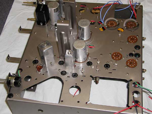
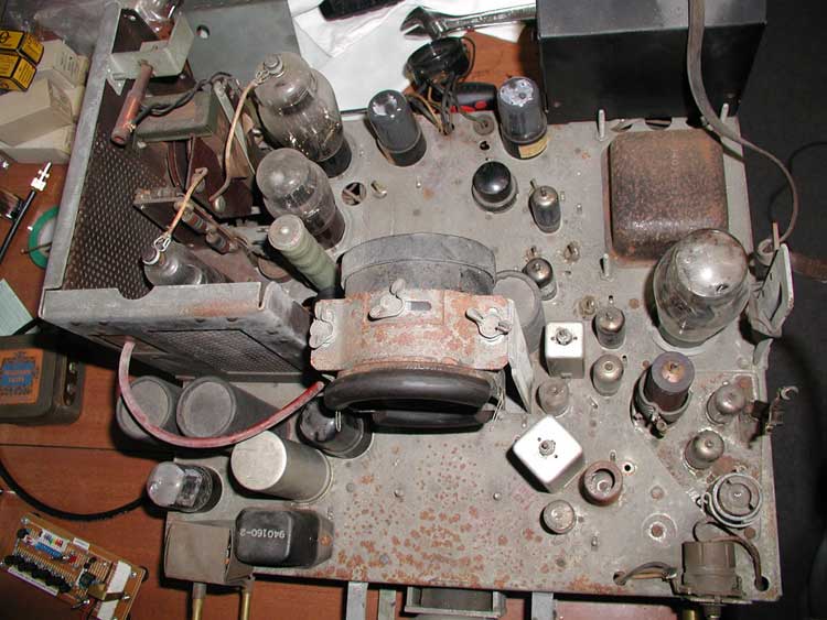
I've modified the connections to the ion trap magnet, each wire now has a small gold plated in line connector, so I can unplug this electromagnet. When the CRT is not fitted, the magnet has a tendency to swing around on its wires and this can mark the chassis. I've also included for interest, a photo of an AWA(AWV) 6SN7. These were a little taller than their RCA counterparts, same specs of course. The chassis before restoration
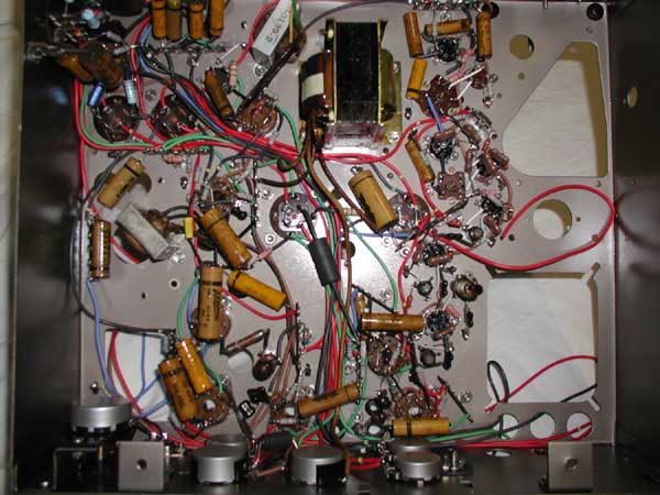
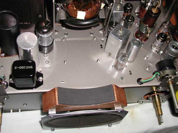
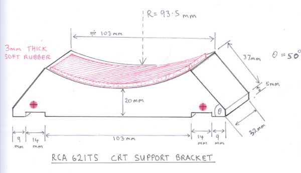
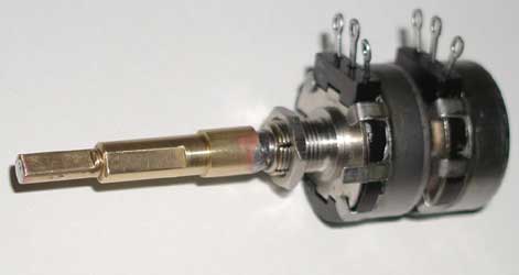
The chassis after restoration The 621 restoration continues well with only minor problems so far. My philosophy of restoration is based on the appearance of the set and a perfect working result, without any intermittent faults or degraded performance. I did my best to preserve all the potentiometers and not replace any unless absolutely necessary, but I came unstuck this time. I usually like to use NOS Clarostat or Allen Bradley 2 watt pots with stainless steel shafts. After powering up the set, I noticed right away that the contrast and brightness pots were worn out and intermittent, despite being immaculately cleaned up and lubricated and appearing to be "reasonable" on a meter. The horizontal hold and Vertical hold pots are ok luckily, they are a bigger more robust design than the contrast and brightness pot dual pot. I had already replaced the vol pot. The intermittent pot is a dual shaft variety and not easy to replace, so I have disassembled a dual Clarostat pot and I'm replacing the resistive elements with those of the correct value from other NOS clarostat pots, and I'm machining new shafts to match the geometry of the original RCA dual shaft pot. I had similar problems with the HMV 904, and had to do the same thing to create pots of the correct values, with the original geometry shafts. I'll send a photo of this later. In the meantime I've attached a photo and sketch of a CRT support bracket for the set made of hardwood (In this case varnished Tasmanian Oak). The 621 relies on the CRT to be mounted properly only when the chassis is in the cabinet, very inconvenient when the chassis is out of the cabinet. So I designed the support as shown in the photo and diagram, it is attached by lengthening the two upper speaker screws and adding two spacers (not fitted yet), and it sits on the speaker brackets. The screw holes are best marked out after the bracket is sitting in place so they are not measured out on the diagram. The CRT sits on it and you can strap the CRT to the bracket with a large sized ( Industrial) nylon cable tie when the chassis is out of the cabinet. The added wooden bracket is such that it can stay put when the chassis is re-fitted to the cabinet, and the CRT mounted in the usual way. The radius of curvature of the cut-out in the wood is 93.5mm, and this reduces to 90.5 mm when the rubber cushion is added to hug the CRT curvature. The bracket geometry ensures the CRT neck is very close to level with the chassis surface. No extra holes need be drilled to fit it. ( Sorry all metric here so to convert millimetres to inches divide the mm by 25.4). The depth of the 14 mm grooves on the added CRT bracket are in the order of 3 to 3.3mm, or about 1/8". I aligned the tuner RF and converter stages and the local oscillator and the video and audio IF's. All very easy to align with the sweep generator without any difficulties at all. I'll send a photo later of a screen image. The performance is wonderful. The Hammond 300BX power transformer runs as cool as a cucumber, and with 120 Vrms. 50 Hz input supplies exactly 6.3 volts rms to the main heaters.
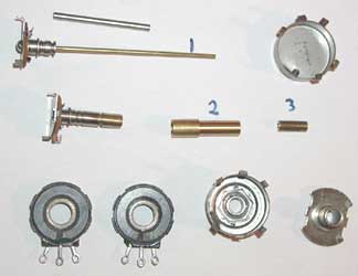
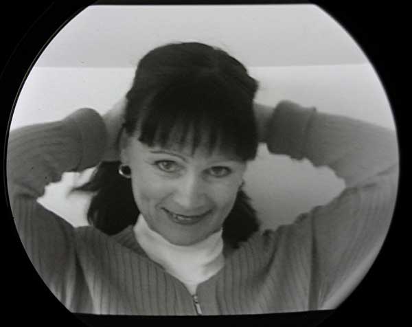
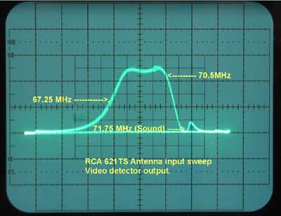
I've attached the photos of how I created a replacement brightness and contrast pot for the 621. I started with a dual Clarostat pot, then fitted a thinner longer central shaft(1) to the rear wiper assembly, then made shaft adaptors(2 & 3), which are press fit and soldered for strength. I got the correct value ( 10K and 500K) carbon tracks out of other single gang Clarosat pots of the same type. Took a while to acquire everything needed. Dual shaft pots, especially with odd shaft sizes like these, are a challenge to replace aren't they? Here is one of the first screen images I acquired on the 621TS. This is with a 7DP4, digital camera photo of the screen, flash disabled. It is a 625 line image (our analog system), the set easily locks unmodified to our H of 15,625KHz and vertical field rate of 50Hz in this case with a small change in value of the vertical blocking oscillator time constant capacitor. I'm still looking for a good 625:525 line converter, preferably with an on board VHF modulator. The screen image you see on your monitor may have curvilinear lines which are a form of "spatial interference", or moire pattern, with the scanning lines on the image and the monitor display. These vary with the magnification of the image on your monitor. If you print this photo out these disappear. Also the darkish wide horizontal band at the top of the image is an artifact, related to the camera's exposure time, vs the frame rate. Here is a sweep of the 621, swept across channel 4, at the antenna input. The basic response of the tuner is fairly flat, but there are some contributions to the final shape so there is some inter channel variation in the over all response, but it's small. The swept response is recovered at the video detector. You can see the absence of response at the sound channel frequency due to the great trapping in this set. Hugo's restoration of the cabinet
|