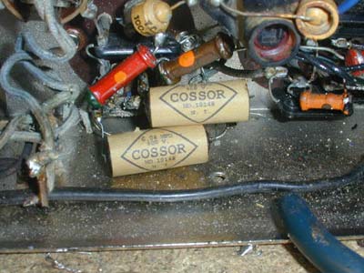
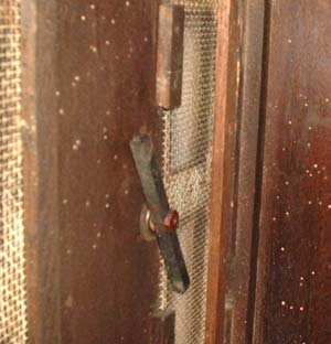
Early Electronic Television Cossor 54 RestorationThe Cabinet: (pictures). The cabinet is in poor condition, with the bottom 2 inches badly water damaged. The base is unusable, and a replica will have to be made. The CRT is a 5 inch electrostatic. The cabinet restoration is complete and a new base has been made of 1/2 inch plywood. The Chassis: (pictures). The chassis is badly rusted. All the components have been removed. Fortunately, the circuit only had to be cut ten times to do this. The tube (valve) socket rivets were drilled out, and screws holding other components were removed. Here is technical information. After the chassis is replated, the components will be re-installed. Then, all paper capacitors will be replaced with modern ones (see the procedure for this). Each electrolytic capacitor will be tested for leakage and capacity. If bad, new electrolytics will be installed inside the old ones. The high voltage (EHT) capacitor also had to be rebuilt. The chassis parts have been replated, and we have reassembled most of the components. Much of the rubber covered wire has rotted and must be replaced. All the paper and electrolytic capacitors have been rebuilt. Some of the paper capacitors were so damaged that I made a new paper covering to go around the cardboard:
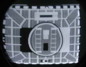
I installed the CRT and tested the set. The horizontal (line) deflection circuits work fine, and the vertical (frame) deflection works, but at the wrong frequency. The focus is not right, and the brightness control doesn't operate properly. The CRT, however, is good. All three pots on the rear of the chassis were bad: horizontal (line) hold, vertical (frame) hold, and focus. Apparently they were damaged by the moisture that rusted the chassis. After replacing them with temporary ones (I will eventually find ones that look much like the original), the deflection and focus circuits work fine. Today I put in the remaining tubes (valves). After discovering that the contrast control was bad I got a relatively good picture. The width and height are adusted on this set by changing resistor values. I had to change the one in the horizontal (line) circuit to get the correct width. Centering is done by magnets mounted in the cabinet - I don't have the cabinet back from the shop, so I can't make that adjustment yet There is also a problem with the linearity on the right side. Replacing the horizontal (line) oscillator tube (valve) solved the problem.
The sound circuits work, but something is intermittent. I have narrowed it down to the output tube (valve), but don't have a spare (a 42OTDD - tetrode double diode, used as audio detector and output). After acquiring a spare audio tube (valve) and installing it, the audio is fine.
|